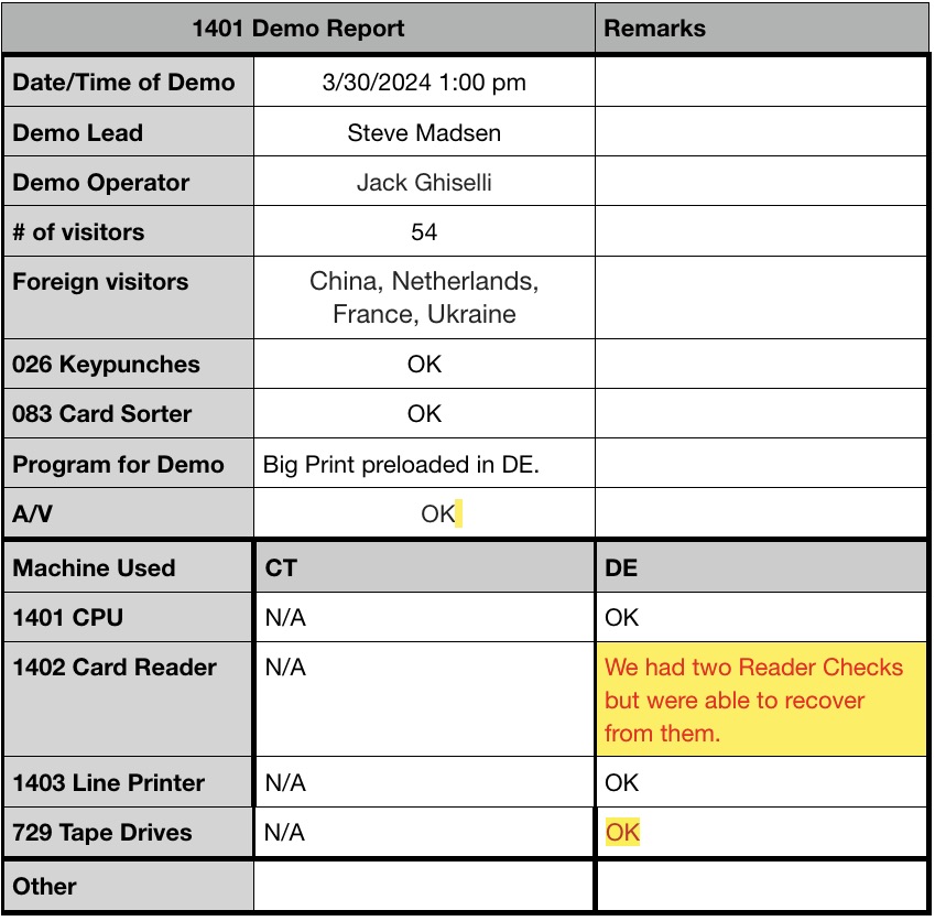
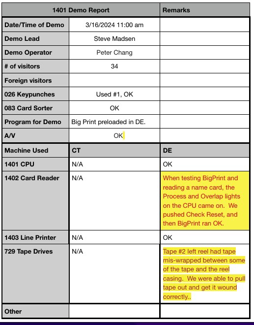
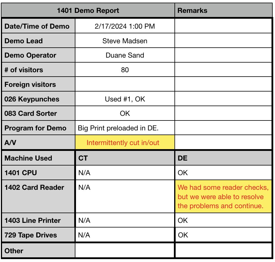
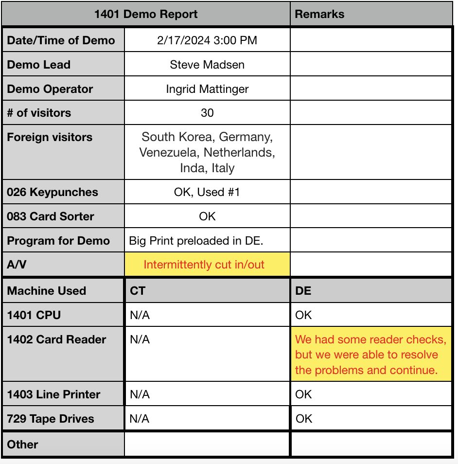
Summary
- Demo went well using DE
- CT 1402 needs help, please
|
Wednesday maintenance reports 3/13/24
001 Keypunch restoration report 03-13-2024
- from John Howard
|
The keypunch was returned to the Demo Lab.
Frank ran Product Test, amd Speed Control failed (too fast). We fixed it by
adjusting the governor.
John
|
- from Ken Shirriff
|
Summary: 1. Investigated the CT card reader. 2. Tested the Hall effect relay sensor that Marc and I built.
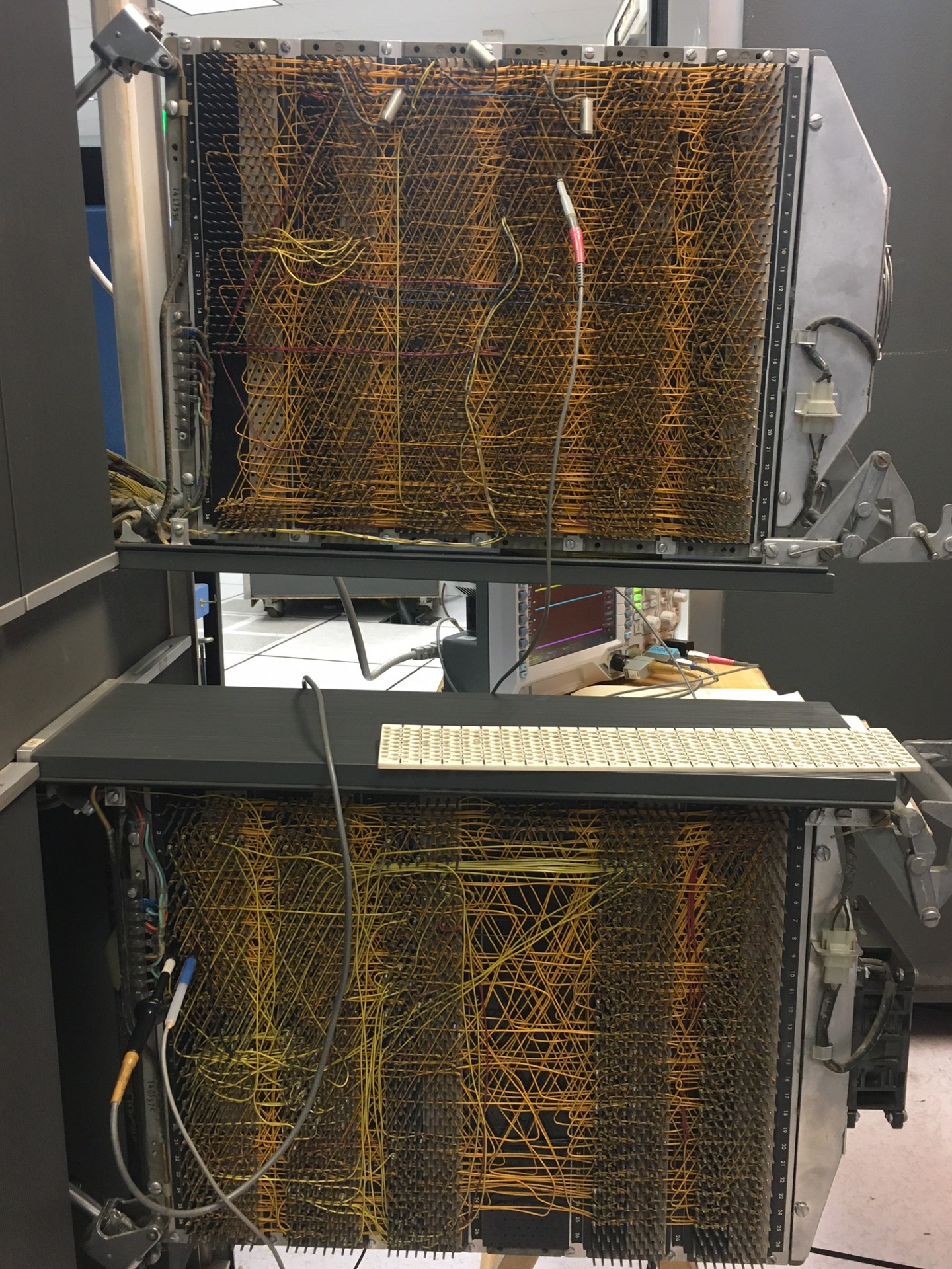
I did some research on how the brush circuits are supposed to work. The problem is that we see solid signals on the brushes, but sometimes cores don't flip, so the wrong data is read from the card. The card reader has two sets of 80 brushes: the first brushes are the check brushes and the second brushes read the data. The brushes are connected through 160 wires to the 160 special row bit cores. When a row of a card is read, the row bit cores are flipped in parallel. The 1401 then scans the cores sequentially to check the data and to convert the hole data to characters.
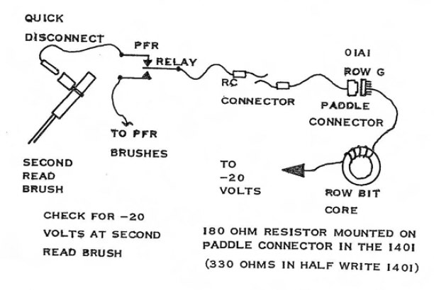
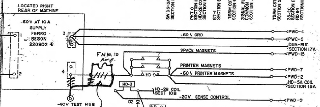
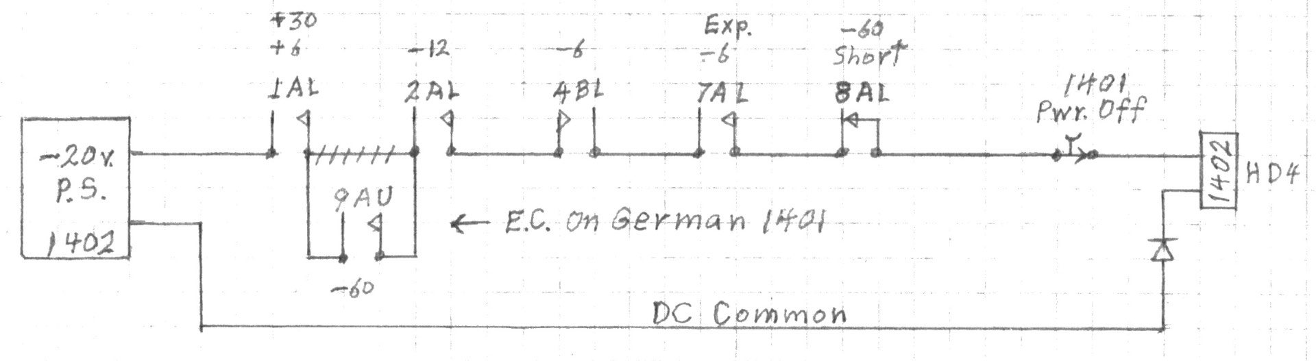
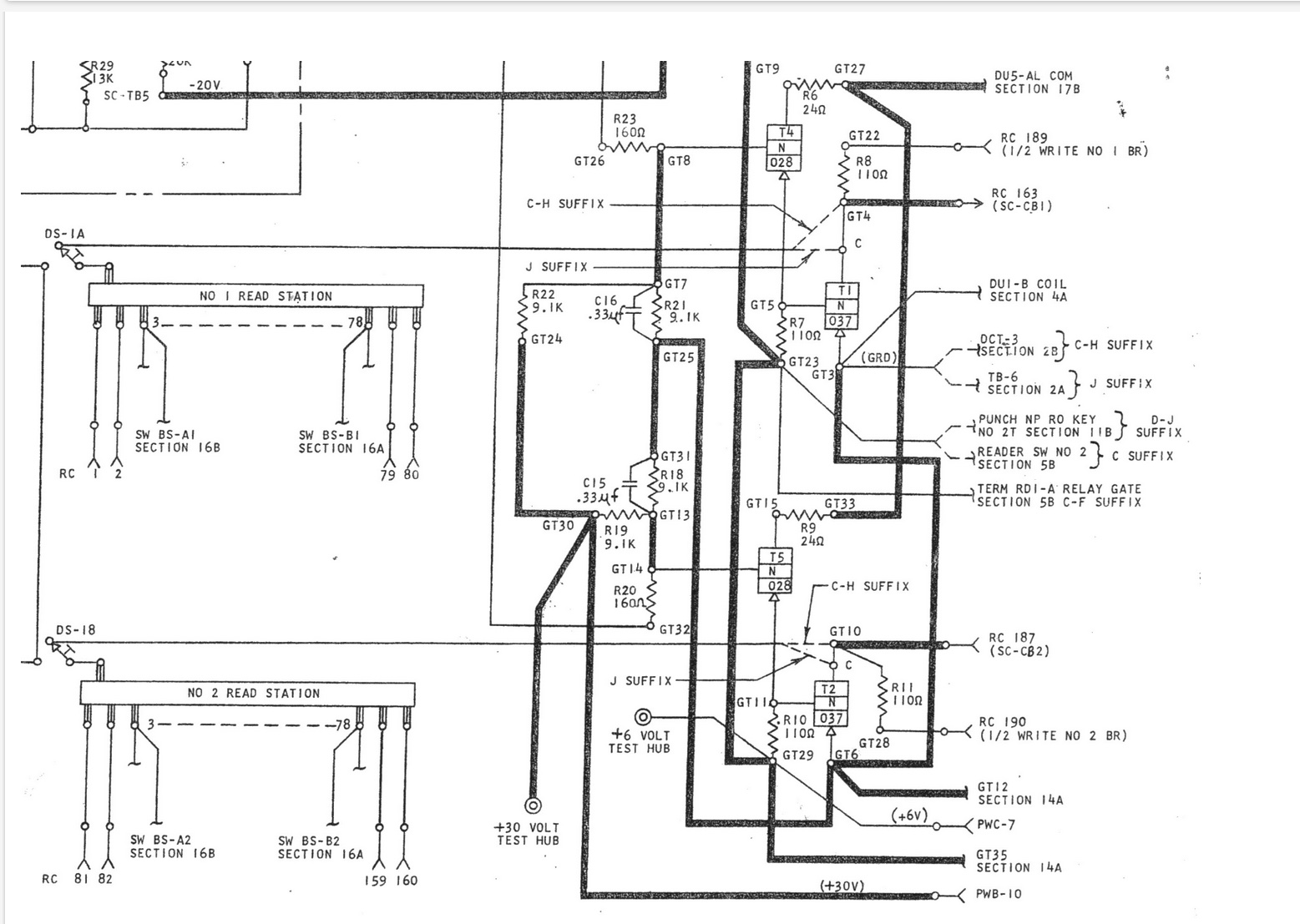
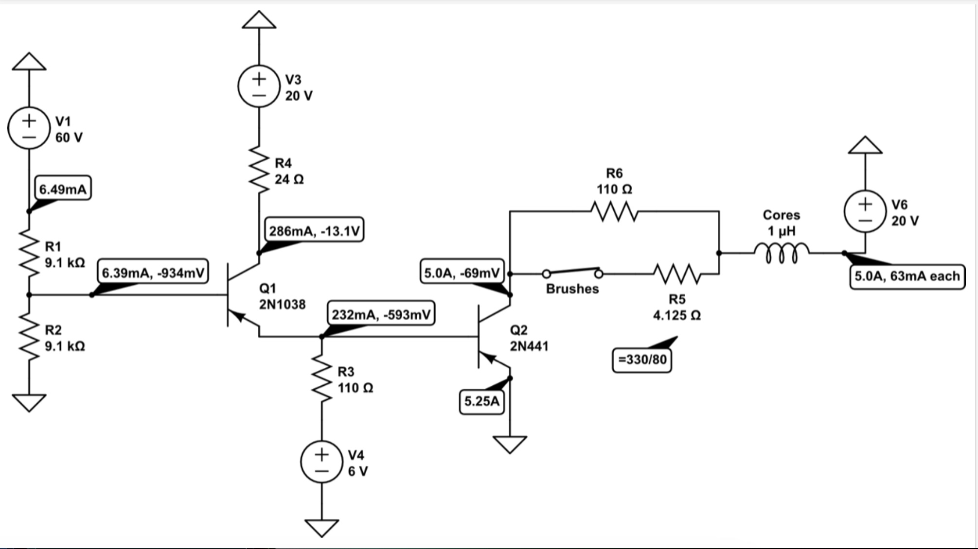
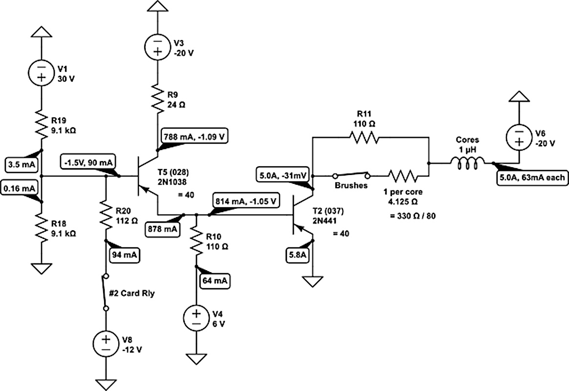
The DE and CT card readers are different because CT uses the "half write" circuit, where part of the current to flip the cores comes from the brush and part of the current comes from the half-write circuit. I made a schematic of how this works:
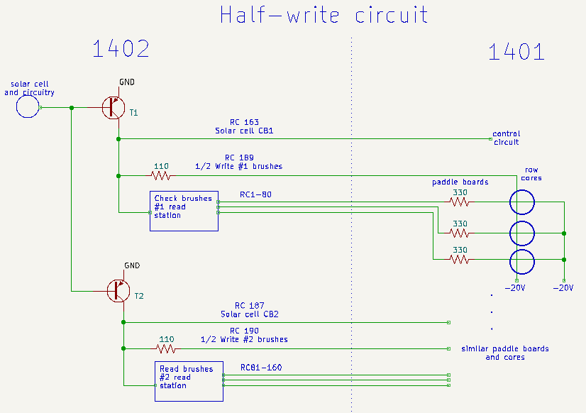
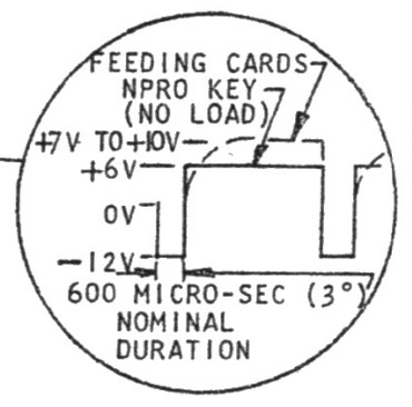
Inside the 1402, the solar cell triggers pulses, one for each card row. The transistors pull the line up to ground. The pulses go to the 1401 for timing ("Solar cell CB"). The pulses also go to the read station, where if the brush makes contact, the corresponding column line is pulled up to ground. The wires go to 330 ohm resistors (one for each column) in the 1401 and then through the row cores, which are connected to -20 volts. Thus, if there is a hole in the card, the current through the corresponding core flips the core. The final path is the 1/2 write line from the card reader to the 1401 through a 110-ohm resistor. I believe this line runs through all the row cores, providing the other half (roughly) of the current to flip the cores.
I haven't found an explanation for the half-write circuit. My guess is that it reduces the current through the brushes, which makes them last longer or more reliable.
One theory for the CT problems is that we're not getting enough current to reliably flip the row cores. The most likely problem would be the brushes not making good contact or having too much resistance, causing not enough current. Another cause could be the solar cell timing making the pulse too short. Changes in the transistor or resistors could reduce the current. Finally, damage or aging of the cores could cause them to need more current. The puzzling part is that the problems are intermittent and only happen on a few cores (e.g. column 3). It's hard to come up with an explanation that would cause problems for just a few cores and not all of them.
Hall-effect sensor
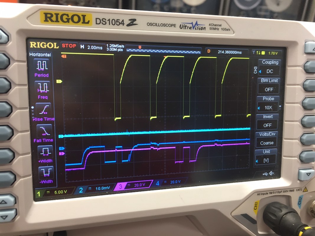
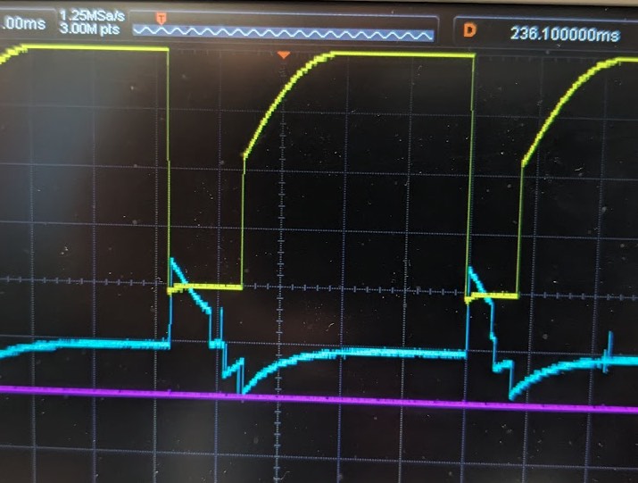
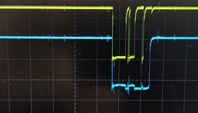
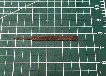
Marc and I built a Hall-effect sensor that allows the status of two relays to be displayed on the oscilloscope. This box plugs directly into the oscilloscope as shown below.
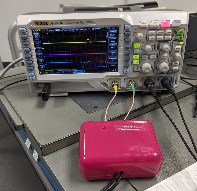
Holding the probe against the relay allows the pick/hold status of the relay to be detected.
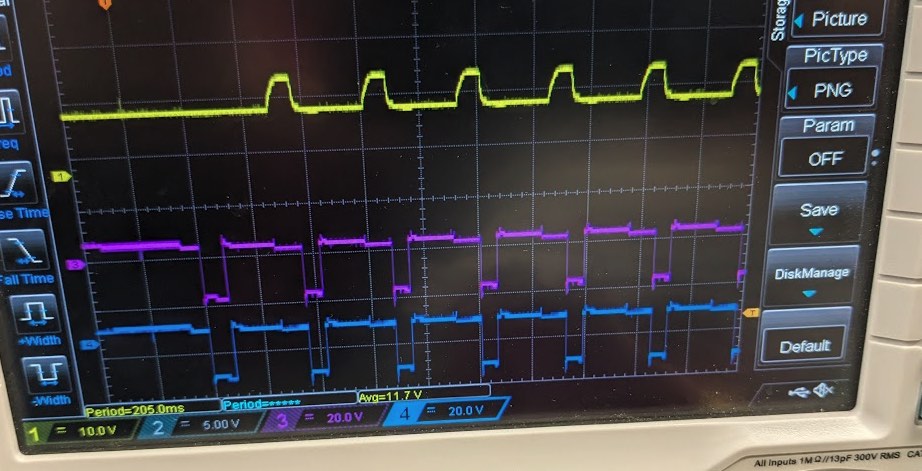
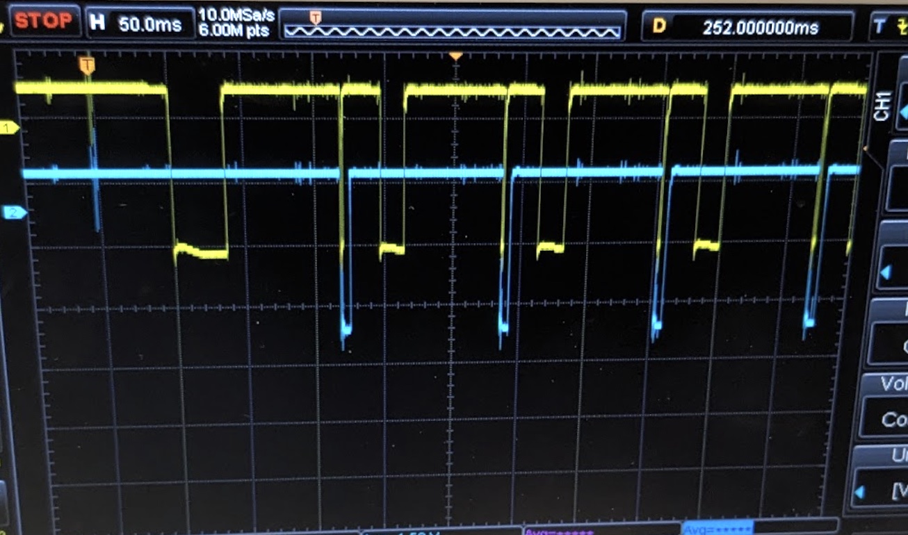
The result is that you can easily look at the relay status over time. The trace below, for instance, shows relay R12 getting picked during an NPRO. The purple and blue lines are the NOT PROC FEED and PROC FEED signals. Thus, you can see that R12 gets picked towards the end of each clutch cycle and is dropped at the beginning of each new cycle.
Ken
|
- from Marc Verdiell
|
DE#3. I could reproduce the symptoms that the tape would not rewind and seemed unresponsive to button presses. The clutch release button would not work either, which had me suspect a vacuum switch or the capstan retract switch. Indeed, the feed reel capstan was found not fully retracted. Pushing it back fully restored normal operation. The fault disappeared after cleaning and oiling the capstan shaft. All 3 DE tapes were verified “operational”, meaning they work for the purpose of the demo. I agree with Jack that none of the tapes appear to work for actual data usage. Much more work needed for that.
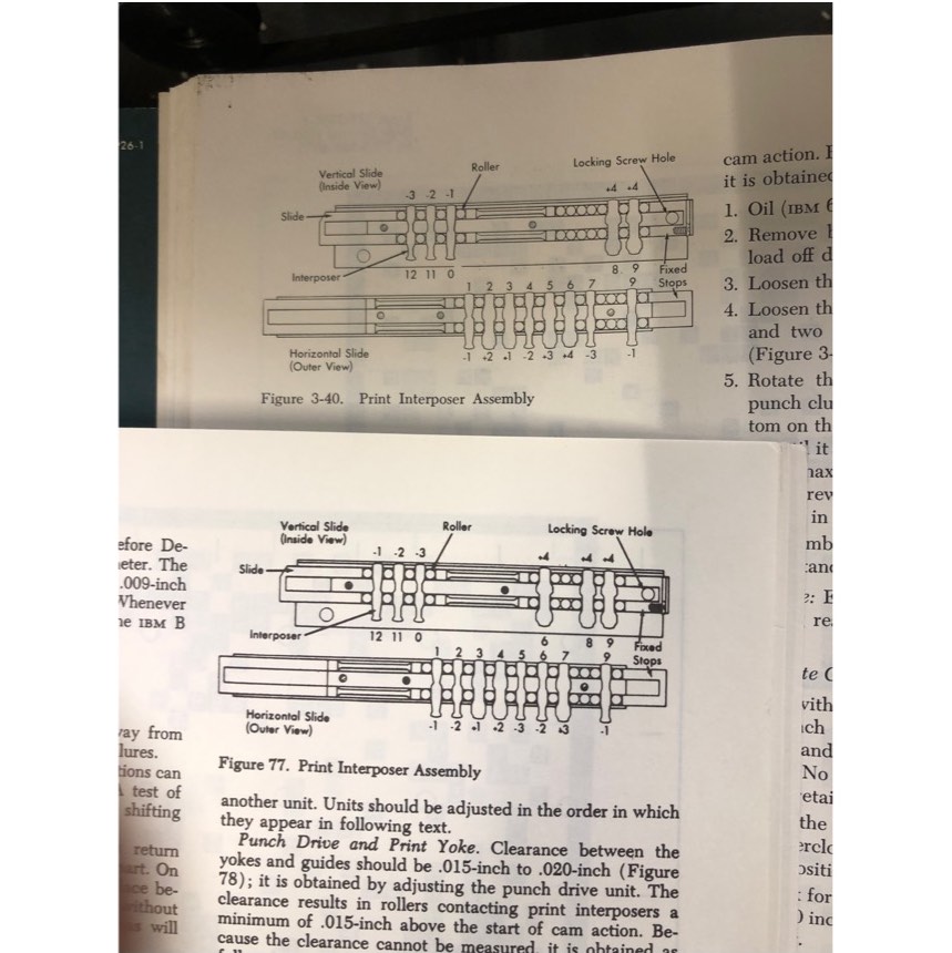
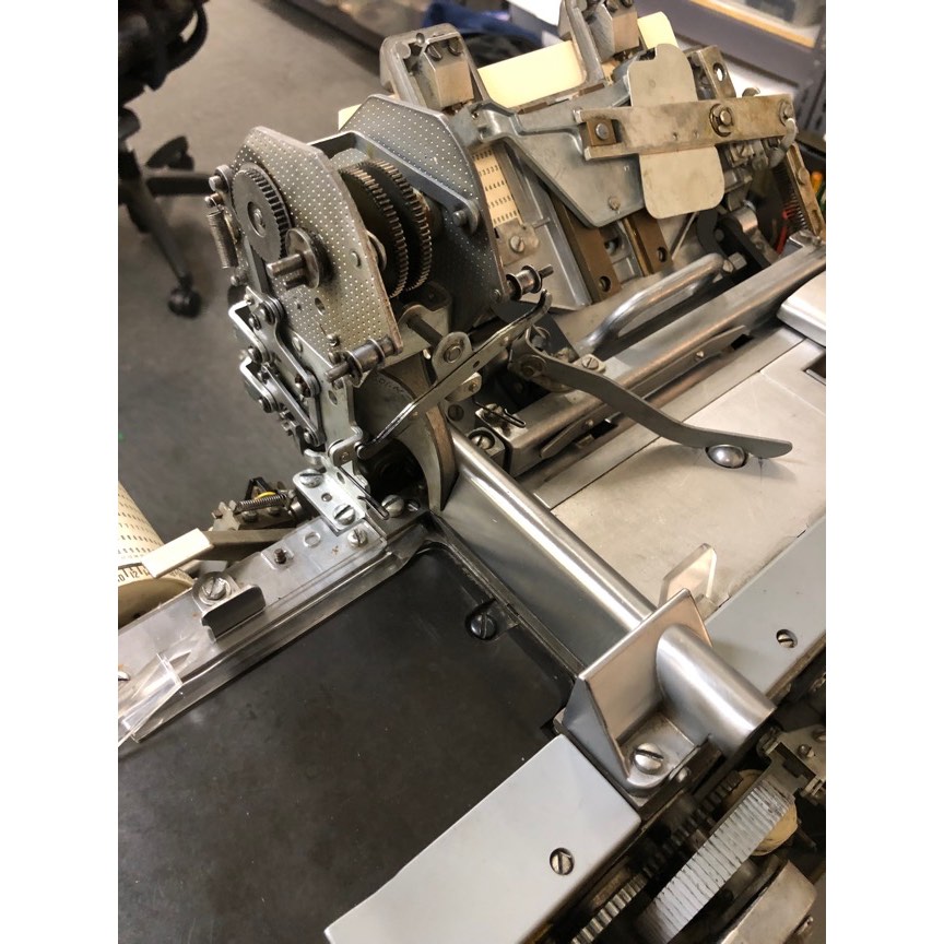
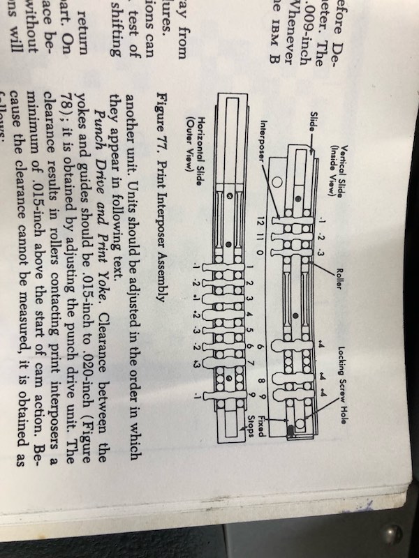
Workshop 026: I took out the printing actuator, and looked at the pegs in the horizontal mechanism. They did not match the ones in the CE drawing, as we had suspected. But they seemed too wrong to account for just a simple reassembly mixup. For example, there is a +4 peg that should not even be present in the horizontal actuator. The vertical actuator was even more off, with a different total number of pegs.
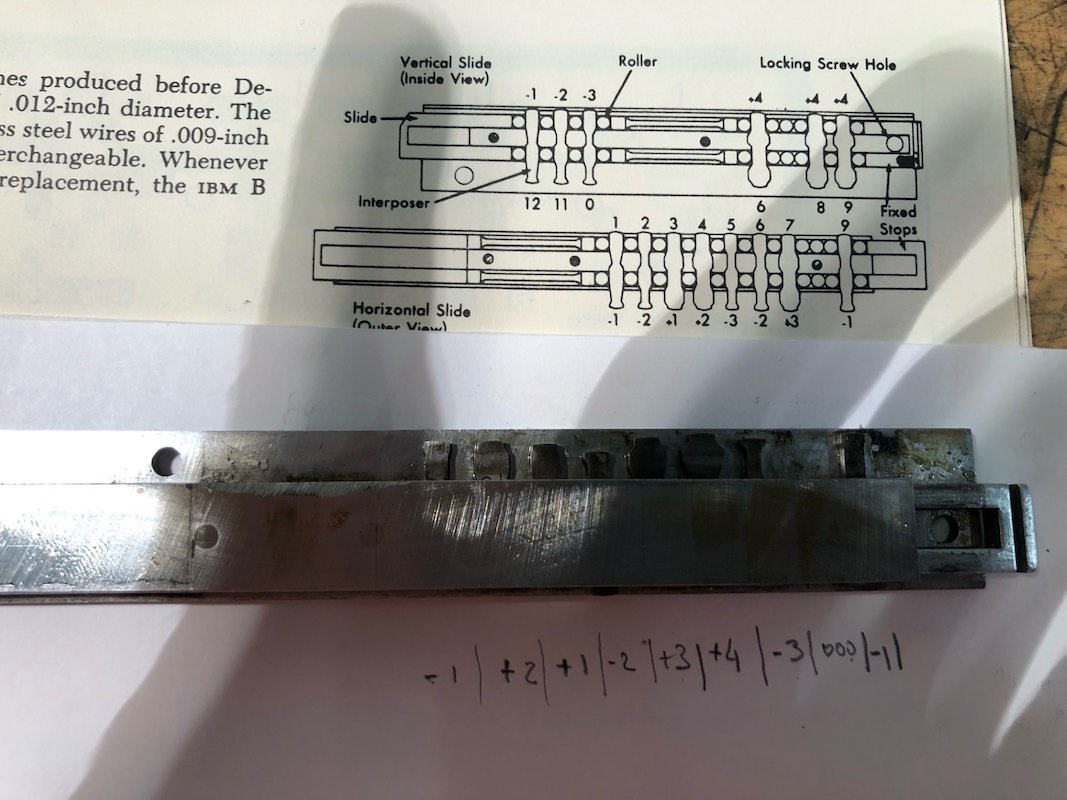
That made us suspicious that this might be a legit arrangement, but for another revision of the printing mechanism. David confirmed the hypothesis when he found another exploded parts manual that matched this very arrangement. That is good news, the actuators were re-assembled properly. We were probably just trying to align the printing following the wrong manual/procedure for this machine version! I didn’t even know that different versions of the print mechanism existed! You learn new old stuff everyday. It could also be that we have a character plate version that does not match the actuator version, but that seems unlikely.
Now that I know the peg order, I think I can realign without the manual. I’ll reinstall everything and try next time.
Marc
|
- from David Clementson
|
CT1402 Reader Check Errors:
We started the day by carefully measuring the resistance from each brush to the common filtered -20V voltage rail inside the 1401. We used a 4-wire ohmmeter to overcome the long test leads' resistances. The experiment was intended to find anomalies or intermittencies of the 1402 brush connections. The resistance measurement results were very consistent, with about a +/-3% variation with the exception of a single high-side outlier in each set (blue = check brushes, orange = read brushes):
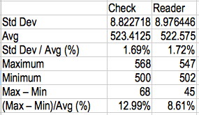
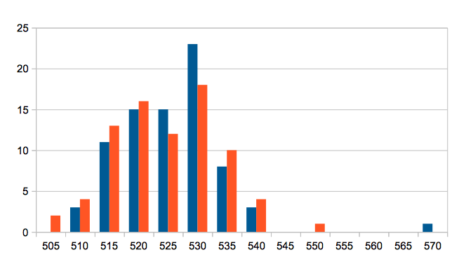
The outliers were #50 Check and #35 Reader.
However the absolute value of ~525 ohms did not agree with the expected value of 330 ohms which is suggested by the color codes of the resistors on the core connection paddles. A quick check of the brush-to-brush resistance was 615 ohms, which is more in line with the expected value of 330 * 2 = 660. So it seems that there is an unexplained ~195 ohms in series with the filtered -20V rail terminal we used.
We then focused on the measurement consistency. While carefully observing the meter for reading fluctuations of the known-suspicious Reader Brush #3, we carefully manipulated the wiring harnesses inside the 1402, inside the 1041, and in between. The resistance reading was solid.
We next resolved to inspect the core write currents. The thinking is that even though they are related, it is the core current and not the brush voltage that is responsible for determining the cores' data value. We tried using a current probe on the common brush while reading a "one-hot" deck (eight cards with one and only one punch per row for each of the 80 columns). Unfortunately, the Agilent 1146B we used did not have enough sensitivity to give a reliable display. Next week I will bring in a
Tek 134
to try the same test. @Marc: if you would be so kind, could you also bring a current probe in case my 134 doesn't cut it?
Workshop Keypunch repair:
After that, I went to help Marc with the keypunch machine in the workshop. It seems that the documentation we have that shows the correct sequence of code plate horizontal positioning interposers only applies to the "base model" unit. The specimen we are working on is apparently not a base model, so needs a different sequence of interposers.
Other:
One thing occurred to me when reading this week's demo report: it seems that we may have been a bit lax when producing card decks because we have assumed that all of the punch stations in the exhibit are correctly aligned and working properly. Robert's observation of crooked punches reveals that at least one of our punch units is producing out-of-spec cards. We should audit all of our punching stations for in-spec card production, and at the very least stop using any punch units that fail to make good cards.
DC
|
|
Wednesday demo report 3/13/24
- from Tim Robinson
|
Scott Stauter and I give the 3pm demo. We had 33 visitors including
from Canada, Taiwan, and the UK. We had two more who came in after the
main demo. Some visitors hung around from a long time after the demo
asking questions. We ran some extra runs including powers of two for them.
We used DE for the demo. Everything worked fine for the main demo,
including all three tape drives.
Key punches were fine and the audio system worked great.
Before the demo Jack left us decks for the two pi-day programs -
printing the image of pi and calculating it to 500 places. We ran these
before the main demo without a problem, but after the main demo in which
we just ran bigprint, we could not get the pi calculator to load again.
It got repeated reader checks. The pi printing deck loaded and ran OK.
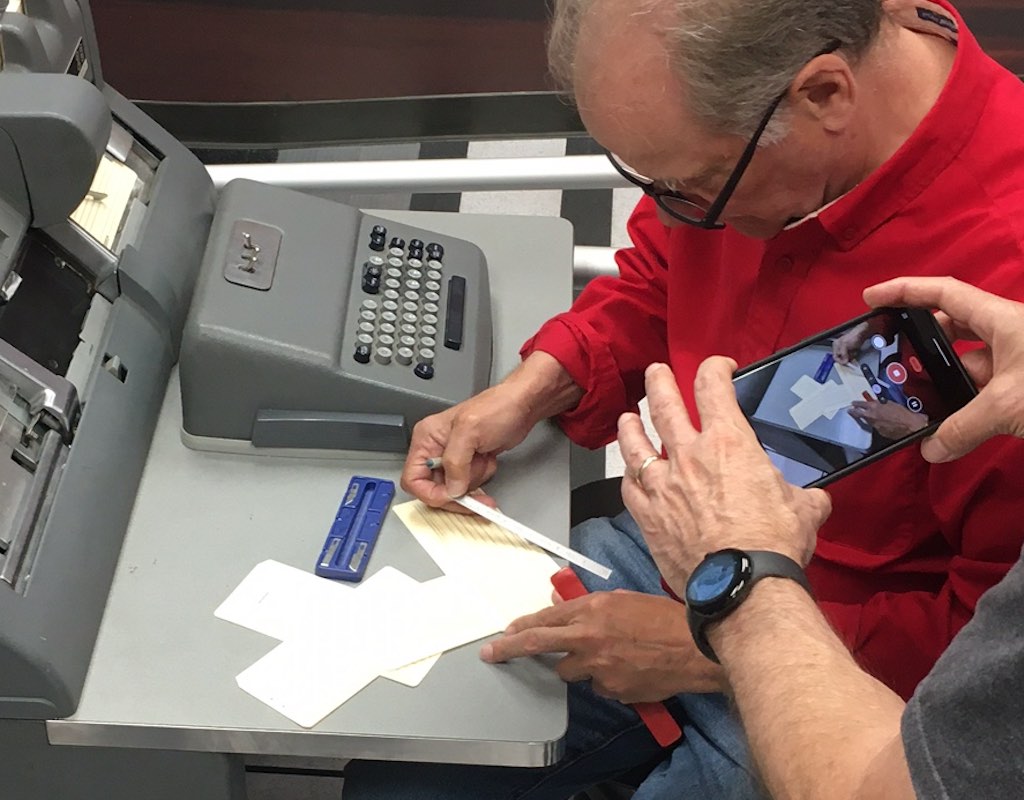
Samuel came over to help. He ran the deck verification program on the
calculation deck and it checked out OK with all cards present and in
correct order but it still persistently got a reader check on the third
card. He duplicated that card, then it loaded and ran fine, even though
we could see absolutely no problem with the original card 3.
Tim Robinson
- from Robert Garner
Tim,
Always good to hear that the hardware cooperated during the demo. :)
.........
>Later, when Sam showed me the problematic card #3, I noticed that the holes slant slightly upward from left to right (i.e,. the card must have been slanted when punched).
All —> Thanks always for the excellent reports and inimitable demo’ing!
Cheers,
— Robert
|
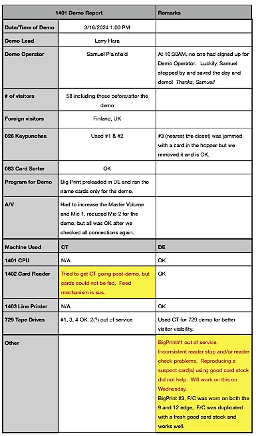
- from Larry Hara
|
Hi 1401'ers:
On Wednesday, 3/13/24, I saw some notes on the BigPrint decks indicating some issues. I tested and fixed what I could:
- - OK on 3/6. Note on 3./9 states that there was a warped card around #10. It might be good to use, but I'll take a look at it on Saturday.
- - Verified good deck to use!
- - Two cards were reported missing. Now replaced, verified, and good to use!
- - OK on 3/6. Note on 3/9 stated that the card reader stopped mid-deck. Not sure if this was a 1402 or card issue. It might be good to use, but I'll take a look at it on Saturday.
Also, it seemed like some of the cards were getting worn at the edges. I'll use a magnifying glass to see where the most wear is observed and replace as needed.
If you encounter a problem with BigPrint, can you leave a note on the deck and I'll look at it as part of routine maintenance? Or just send an email to me.
Happy Pi Day !
Larry
|
|
March 12
- from Jack Gjiselli
Pi Day (3/14) will be this Thursday. I came in today and created an object deck for the Restoration Team's 1401 demo program "PI500", which computes and prints the first 500 digits of Pi. It's a reasonable representation of 1401 computation speed. Perhaps we could run it during tomorrow's 3:00 Demo?
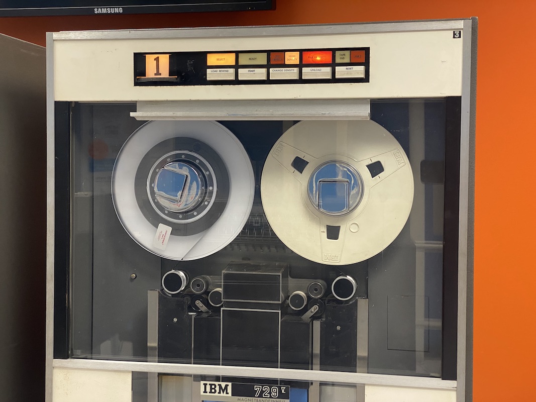
I came in to see if it was possible yet to try to build a tape-loadable demo on CT. The CT1402 was definitely usable, and the PC to 1401 system was also running. Unfortunately, the CT729s didn't cooperate.
All CT729 drives run OK with the TAU
CT729 #2 and $4 won't select LOW DENSITY (required for fewer tape errors)
CD729 #1, 2, & 3 won't run with software (Tape Exerciser)
CT729 #4 ran with the Tape Exerciser, but hung at end of reel and got errs at HIGH DENSITY.
Just before CT power-down, CT729 #2 refused to unload.
Jack Ghiselli
jghiselli@sbcglobal.net mobile 1-408-839-1051
|
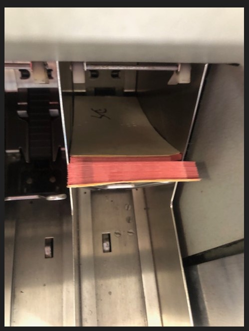
DE 729 Tape Drive #3 Stuck/Nonresponsive
- from Arda Ugur, March 11
|
Good evening,
I was at the museum today along with Jack, Paul, and Pat for my 1401 Demo Operator training. I powered up DE machine [only] for demo purposes. While everything else behaved and worked as expected, 729 #3 became nonresponsive very early on, as detailed below.
- Loaded tape manually by rotating the right reel clockwise.
- Pressed “Load Rewind” button. This engaged the read/write head.
- Pressed “Start” button. This started moving the reels.
- At this point reels on all three 729 units are moving as expected.
- All 729 units’ dials are set to [1].
- Pulled out TAU frame on 1401 DE machine.
- Ensured that all switches and dials are set according to the demo operator manual.
- Pushed “RESET” switch up and released.
- Pushed “START” switch up and released.
- At this point all 729 units except #3 is working as expected. I am letting the tapes to continue to run until about more than half of tape is transferred to take up reel so that I can demo fast rewind.
- As part of demo practice, I pressed “RESET” key to stop tapes, then decreased tape speed in TAU frame (by increasing “GO DOWN TIME” and then finally “START” key to run the tapes at a slower speed before demonstrating the high-speed rewind.
- Towards the end, demonstrated high-speed rewind by pressing “LOAD REWIND”
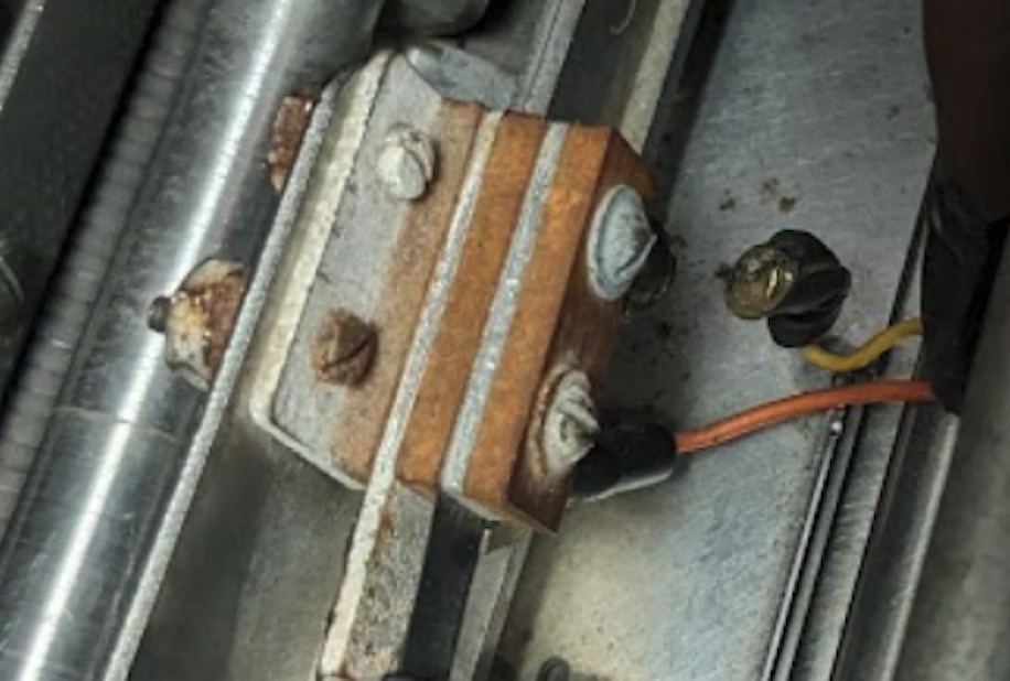
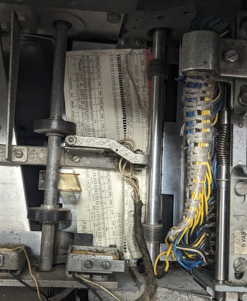
Up until step (12), tape units #1 and #2 behaved as expected. We were unable to debug the issue with #3. After the demo, pressing “RESET” button, trying to disengage the read/write head by pressing “UNLOAD” or “LOAD REWIND” did not resolve the issue. I powered down and powered up 729 unit – which made the reels move a little but did not resolve the issue. I also powered down and powered up the 1401 unit – which made the reels move a little but did not resolve the issue either. At this point, the buttons on DE 729 #3 are not responding and the wheels are not moving.
There was no smoke, fuse indicator or any other unexpected behavior on the unit. It simply appears to be “stuck”.
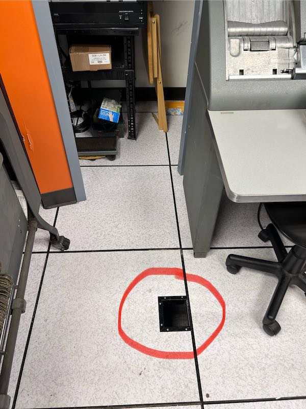
Please see the attached photo.
Regards,
Arda
|
CHM 1401 Demo - Special Group Thursday 3/21 1:00 PM
- from Jack Ghiselli
|
Duane Sand and I gave a 1401 demo to a specially-scheduled group of 8 people on Thursday 3/21 at 1:00, plus about 10 random visitors who wandered in before or afterwards. International visitors were from Canada and France.
We ran the demo on DE. Other than a couple of Reader Checks and Reader Stops on the DE1402, the hardware ran fine.
After the demo, we tried running on CT. The Restoration Team has been doing a wonderful job because we were able to load card decks on the CT1402 with I/O Check Stop in the normal ON (Up) position. This is a huge improvement -- apparently all read brushes and check brushes were working correctly. Big THANK YOU shout-out to the Restoration Team.
With hopeful optimism, we tried running actual software (instead of the TAU) on the CT 729 Tape Drives. Drives #1, #2, and #3 would not run on the Tape Exerciser (Ron 2.1). Drive #4 ran until it reached the end-of-reel marker and then hung.
We still hope eventually to try Tape-resident demos. To try this, we need CT with at least one (1) 729 Tape Drive which will run with software. Ron 2.1 is a good test for this.
Jack Ghiselli
jghiselli@sbcglobal.net mobile 1-408-839-105
|
- from Duane Sand
|
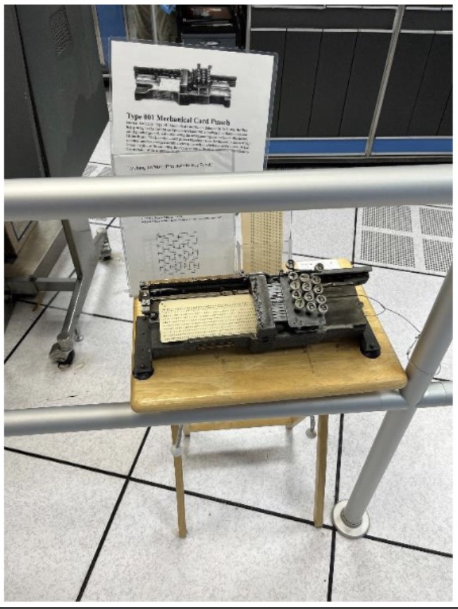
The 001 manual card punch is back, thanks! It is tethered to a guardrail post quite close to the CT printer. It is now difficult to walk in front of the printers without knocking into it and printers and knocking off the microphone belt radio. Moving the 001 one foot further away would give enough clearance.
|
|
IBM 1401 Demonstration Sat. Mar. 9, 2024
from Samuel Plainfield - 11:00 AM Demo
|
Folks,
We had a keenly riveted group of about 35-40 people (~20 or so more afterwards) this morning. Duane Sand and I gave the demo and the microphones were absolutely perfect! It was a delight. Thank you to everyone who has put in efforts to get these fixed, I know it's very frustrating and difficult to diagnose. We really appreciate it!
I powered up CT and we used that exclusively as a dramatic vote of confidence -- I did not power up DE at all.
Interestingly, on the first go, I observed no reader checks when pre-loading BigPrint in advance of the demo. I attribute this to luck; as later on after the demo, attempts to load known-working good decks of Lincoln would result in PROCESS errors which I suspect are due to intermittent read brush errors. I/O check remains turned off on CT at all times for now.
In any event, all of the equipment worked great for our demo including the keypunches, sorter, tape drives and printer; no cards were munched.
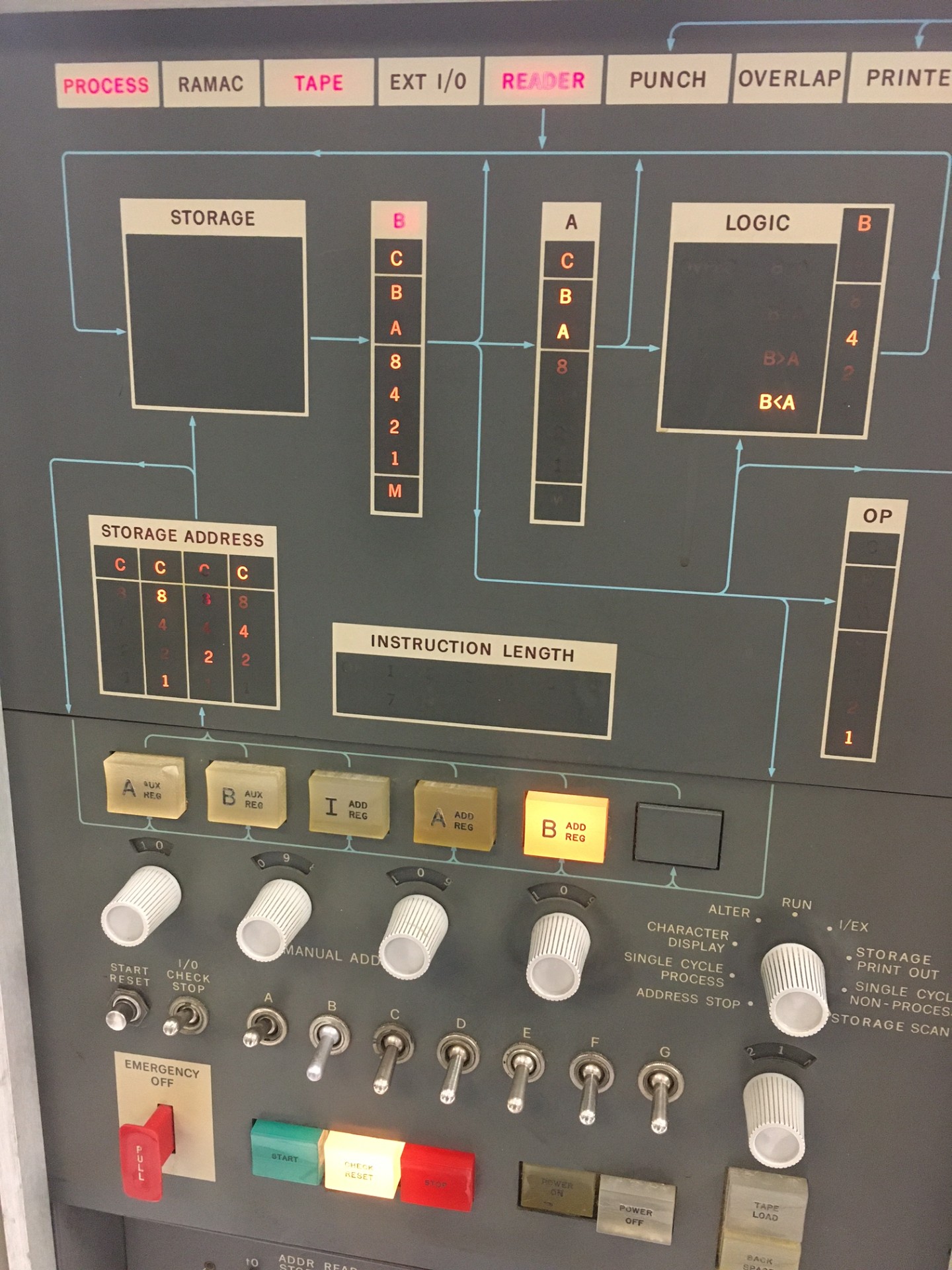
Minor note: We have a burned out bulb in address register A on CT because I noted an even set of digits at one point without an error light.
That's about it for now,
~Samuel Plainfield
|
from Duane Sand - 11:00 AM Demo
|
The mikes worked so well, that mike#2's amp worked great at a nominal setting matching mike#1. Thanks!
In the afternoon demo, there was some anomalous behavior with the rightmost CT drive. During a Rewind op, it stopped fully while mid spool. It completed normally whe we hit Rewind again. Also, both leftmost and rightmost CT drives had no tension on the right hand tape when parked in unload position.
One of the BigPrint decks loaded successfully on both DE and CT. Two other BigPrint decks stopped consistently on DE at the same card when retried. I think this was some edge flaw in those cards. Afterwards, I tried to replace those cards with orange dupes made on middle keypunch with printing turned off. But those copies with identical holes stopped the loads in same way. Huh. A binary card duplicated on the keypunch furthest from closet dropped some punches so could not be trusted. This was with printing temporarily off.
It was fabulous to have both 1401s usable today. Yay!
|
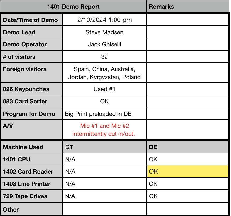
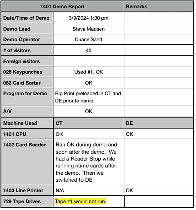
- from Stephen Madsen - 1:00 PM Demo-
|
Restoration Report for March 6, 2024
- from Marc Verdiell
|
I fixed DE#3 tape and its burned up vacuum pump stator. All 3 DE tapes appear to “work” now, “work” being defined as being actuated from TAU for demo purposes. Details below.
Went to Yosemite (thanks Aurora) and borrowed a new stator from a parts tape. It was the correct 220V and 50Hz, so the donor tape must have been from the DE system originally. After cleaning, it appeared to be in perfect condition. Remounted it on top of DE#3 vacuum pump. Reinstalled the pump along with new rubber vibration isolators, and also put missing covers back on the vac switches while I was at it. Tape checked OK. Moved the terminator back to tape 3 and verified all DE tapes operated properly from TAU.
Arda and Ken had a temporary hiccup later on. DE#3 tripped breaker 4. This happened after Arda reinstalled yet another missing vac switch cover. We took the cover off, reset breaker 4, and problem went away. Not sure if the cover caused a temp short, or if it was something else.
I am looking at options for having a shop rewind our two burned stators, from the head load motor and the vacuum pump motor. I dislike the idea of stripping the precious few other tapes we have when we could repair the parts instead.
Marc
|
- from Ken Shirriff
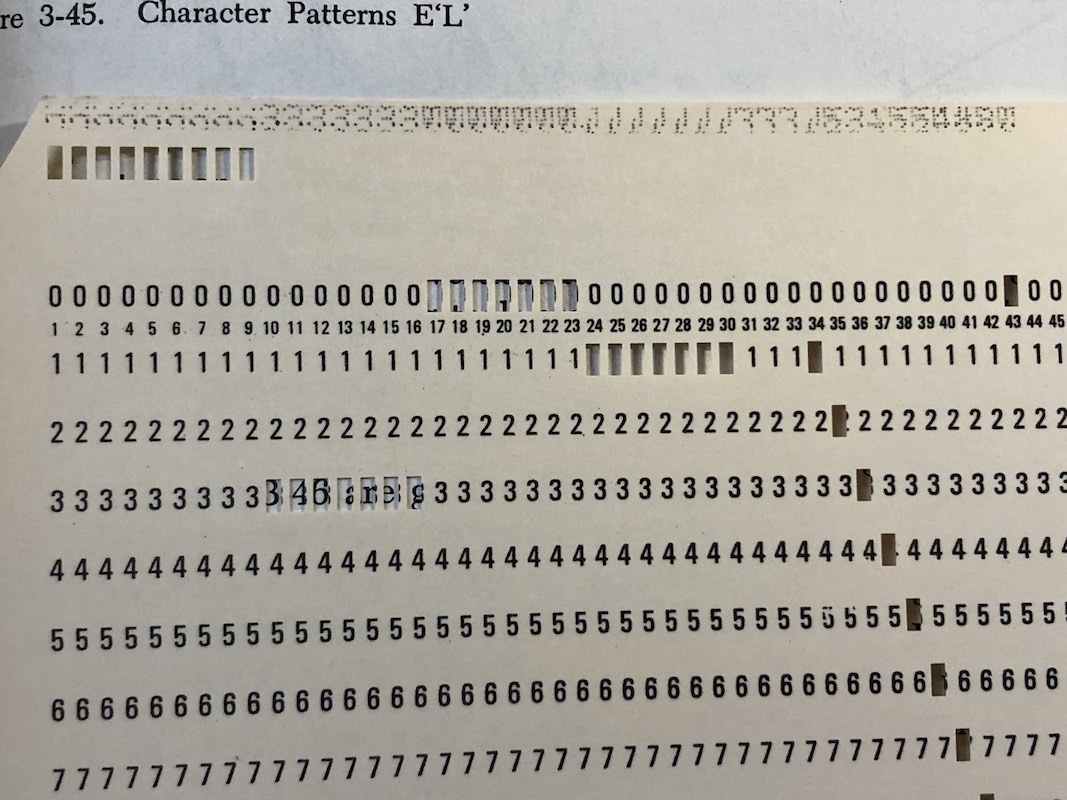
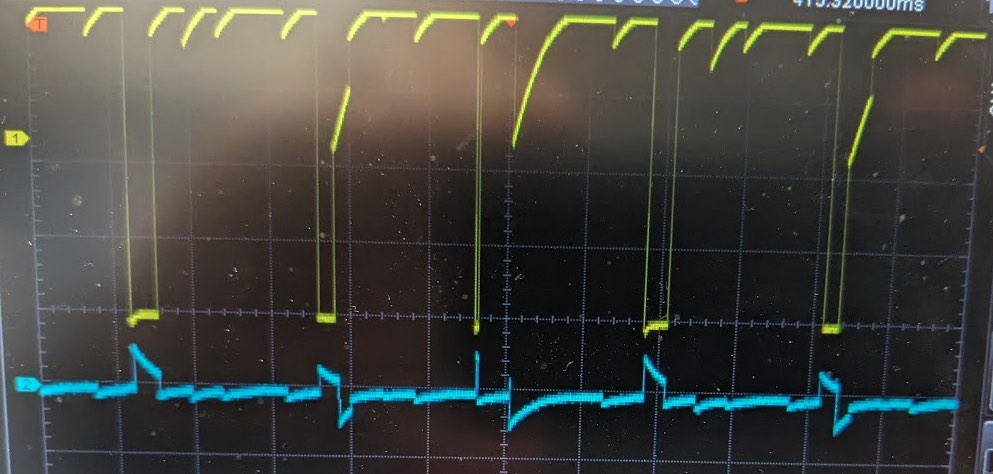
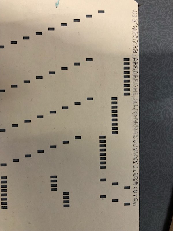
I investigated the CT 1402 card reader that has reading problems. I came up with a way to look at the card hole signals inside the 1401 as they come out of core. The top line shows the 80 holes read by the check brushes (RD1) and the bottom line shows the holes read by the read brushes (RD2). This is an all-4's card, so there should be 80 holes. You can see the three failing check brushes as gaps in the signal.
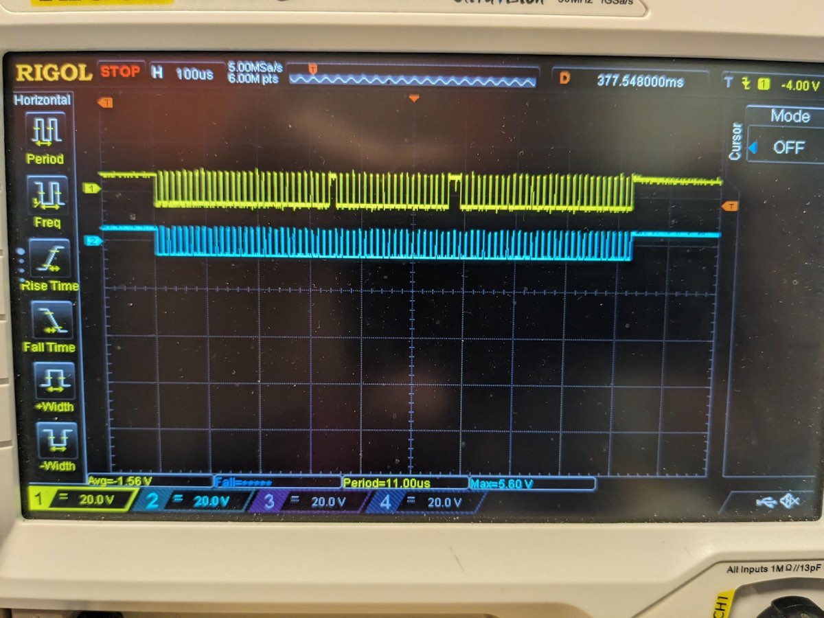
To get this data, I put a probe on RD1: 01B7 A09B and a probe on RD2: 01B7 A09F. The advantages of this compared to a storage scan are: a) You can see all 80 columns of both brushes at once. b) You can tell if the problem is the check brushes or the read brushes. c) You can look at a dozen cards at once.
The failing brushes were usually the same ones, but sometimes there were more or fewer failures. In particular, we also saw a lot of failures on read brush #3.
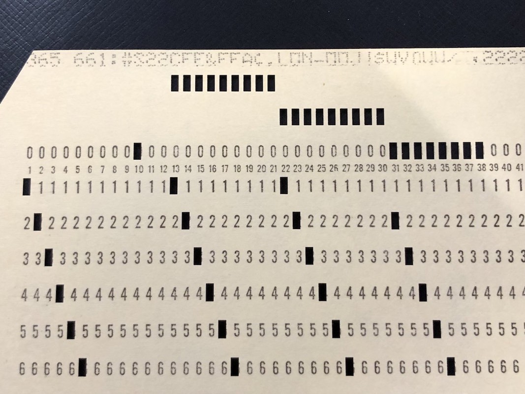
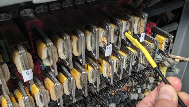
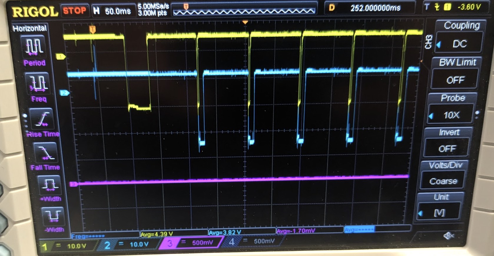
The other experiment was with David, scoping read brush #3 inside the 1403 directly at the brush block as Samuel loaded all-4's cards. The curious thing is that we saw good pulses for each card (very narrow purple pulses), aligned correctly with the solar cell (blue). But the 1401 didn't see these holes.
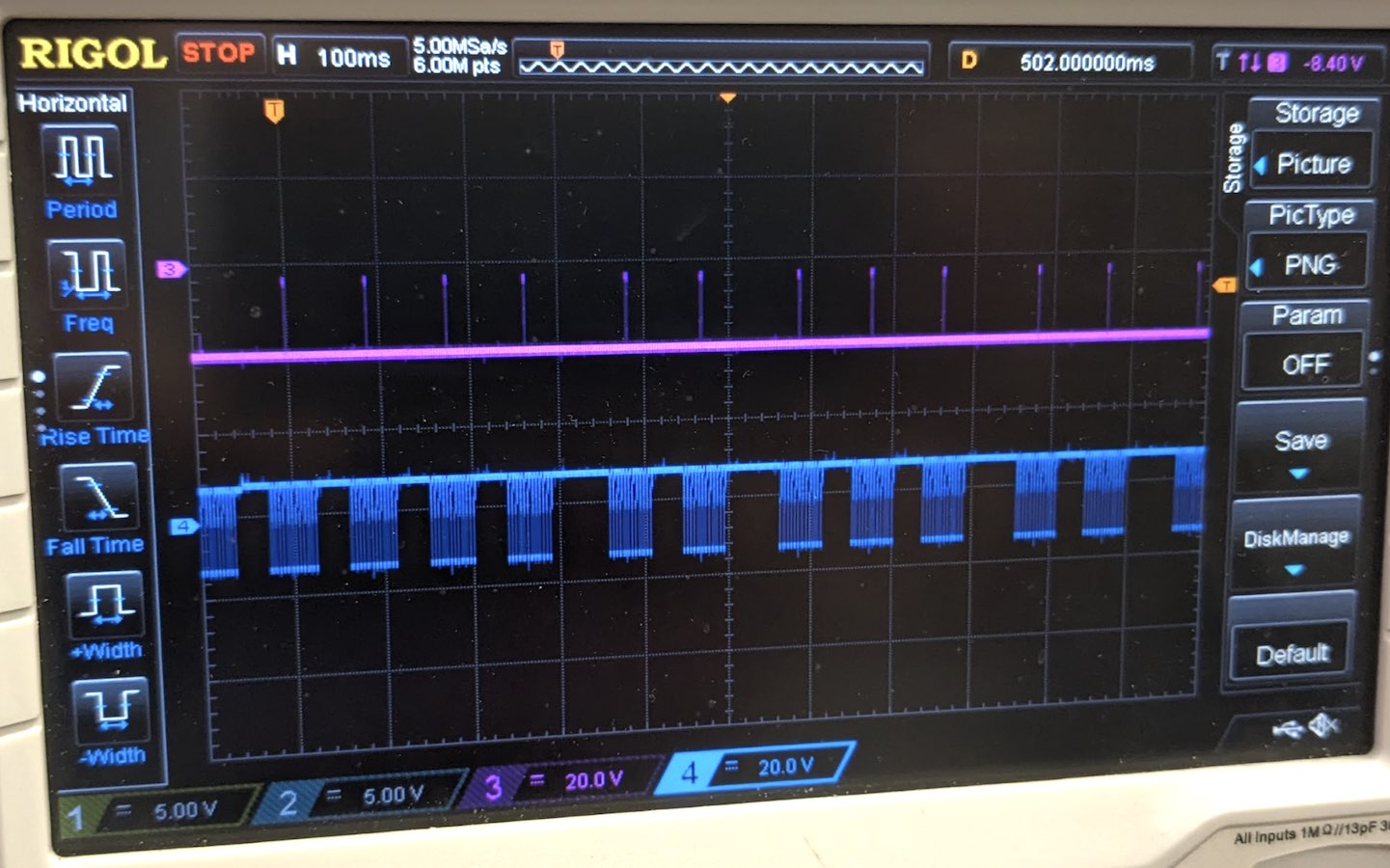
This is a surprising result, since it shows that brush 3 was working okay, but the data read from cores in the 1401 is bad, so the brush itself is not the problem. The problem must be something intermittent between the brush and the core plane. Maybe bad wiring? Maybe a weak core that doesn't always flip?
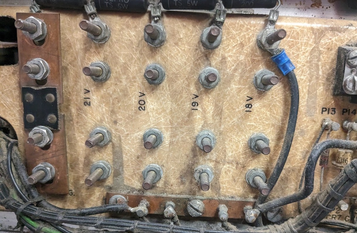
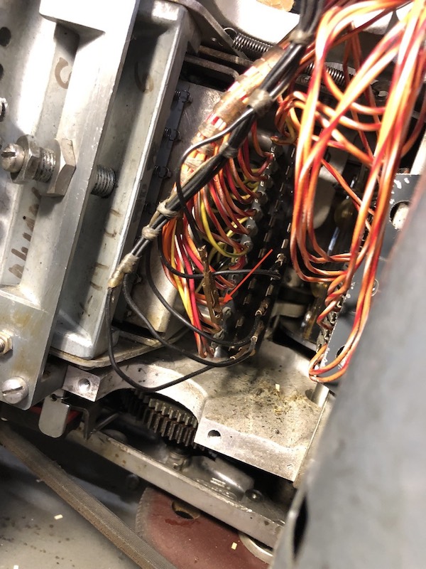
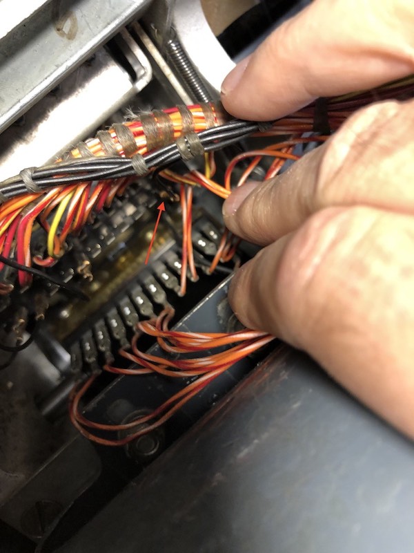
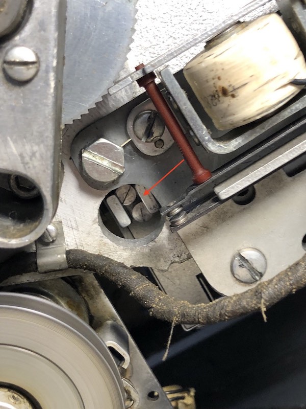
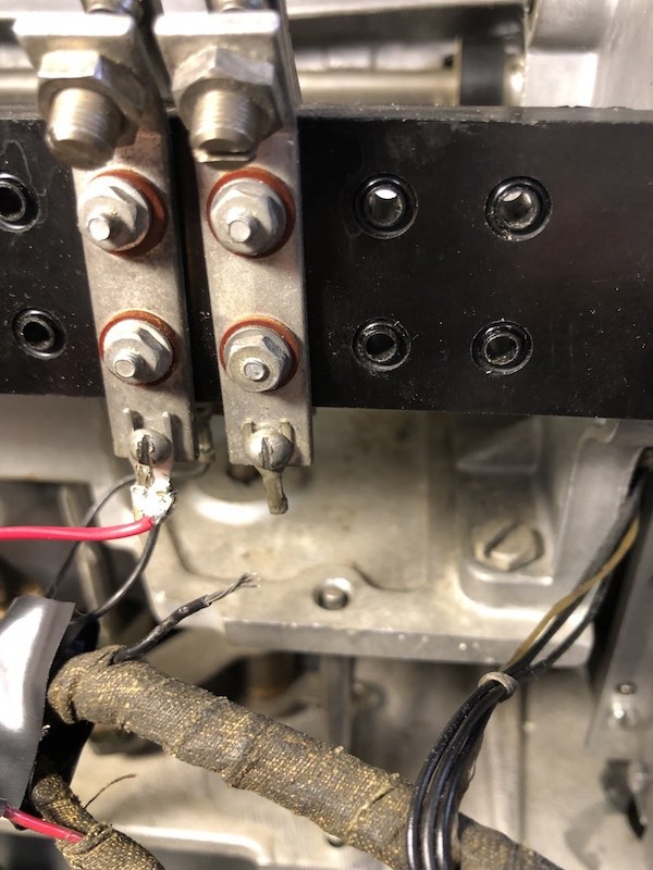
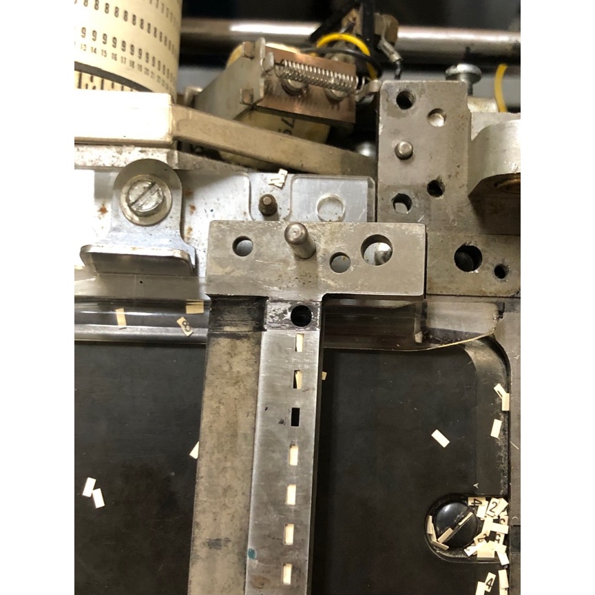
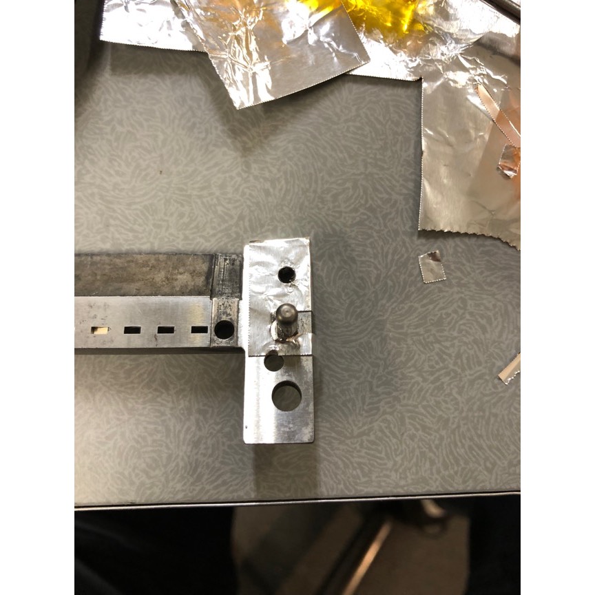
The brushes are wired to paddles in the 1401 with resistors (below), and then to the special read core plane.
CT has 330-ohm resistors while DE has 180-ohm resistors on the paddles that connect to the cores.
The paddles are hard to access since they are wired directly to the cables from the 1403, and are not in a gate.
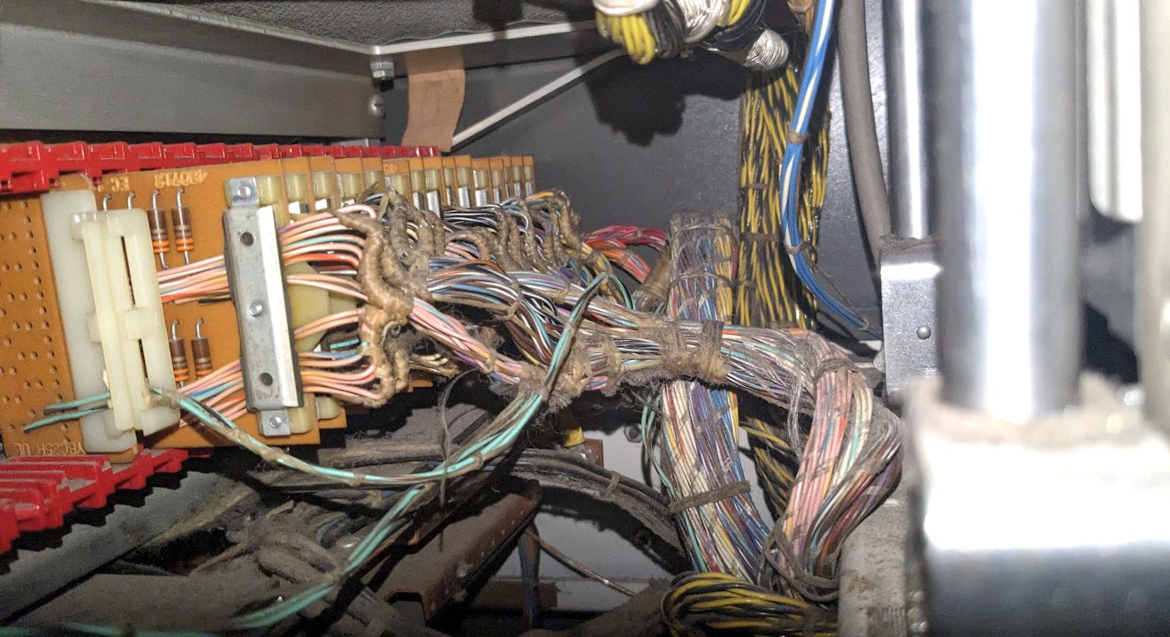
The signals can be accessed when the console panel is opened. The scary thing is that these lines go directly through the cores to -20V, so if you short one of these pins to ground, it will destroy the core stack.
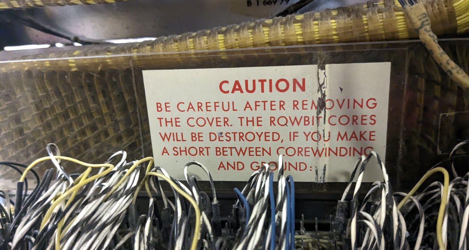
David has some ideas on how to do end-to-end resistance measurements between the 1401 and the 1403, which should help pin down the problem.
Ken
|
|
March 6 1401 Demo
- from Scott Stauter
Tim Robinson and I gave the 1401 demonstration to 28 visitors at 3:00, and 9 others afterward. We used DE 1401 for this demo. The audio equipment worked perfectly today. The keypunches and sorter worked fine. The DE 1402 worked well, with only one reader check. The 1403 and the three 729s worked well.
Our visitors were from Australia, Russia, and Taiwan.
Scott Stauter
|
IBM 1401 Demo Report 3/2/24, Saturday, 1:00 PM
- from Larry Hara
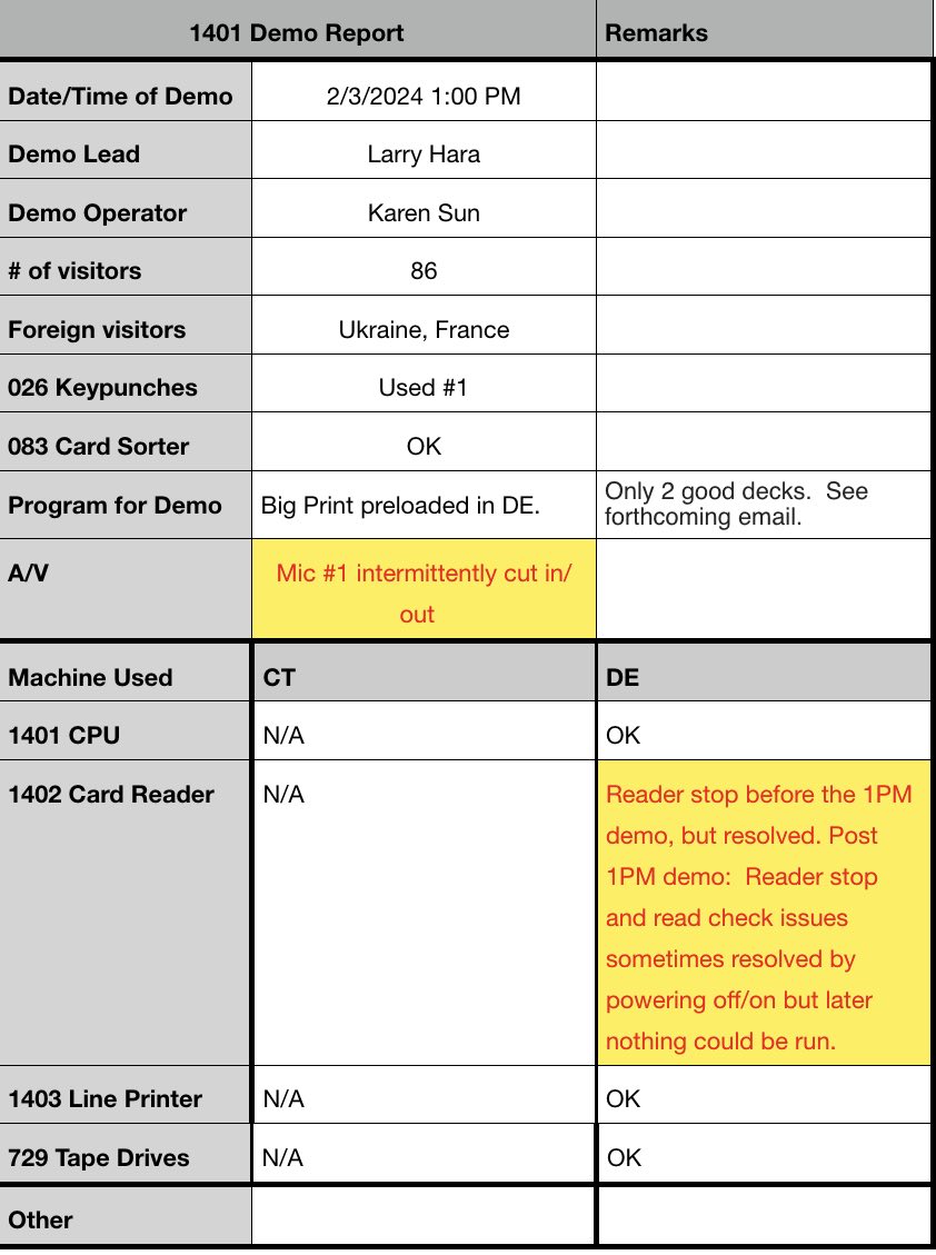
Summary
- Extremely busy day, but successful in demonstrating the equipment to the visitors
- CT 1402 encountered unrecoverable stacker errors
- DE 1402 had reader stop and reader check errors
- BOTH mics have problems and need repair
- All DE 729’s remain out of service
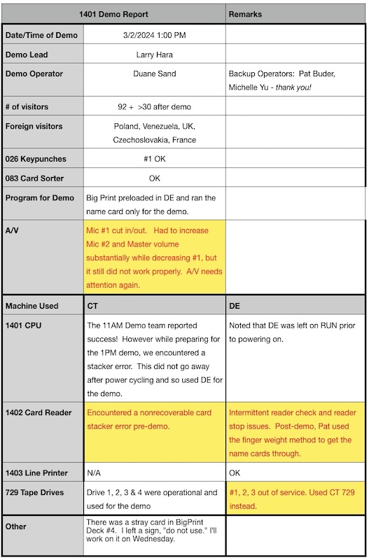
Larry
|
Restoration Report for Feb. 28, 2024
- from Ken Shirriff
|
Summary: found problems with the CT 1402. It now loads and runs programs successfully. It gives Reader Checks but these are from the check brushes; disabling I/O stops allows it to be used.
Details: I found two intermittent problems with the CT 1402. First, relay 11 #1 CL DELAY was giving bad or truncated feed signals, probably due to dirty contacts. Replacing the relay fixed this. In this picture, the yellow signal (NOT PROC FEED) should match the cyan signal (PROC FEED), but you can see that the yellow signal is messed up:
The second problem was that LOAD caused a single clutch cycle ending with a READER STOP. Checking the various stop paths showed that the clutch check circuitry was triggering the READER STOP erroneously because relay 10 CLUTCH CHECK wasn't holding. David suggested that diode RD19 might have too much resistance to activate the hold coil. I tried to clip the scope on RD19 and the probe went right through the lead, which had fallen apart from corrosion! David soldered the diode back together and LOADs worked successfully.
Remaining issues with CT 1402:
- The check brushes cause a lot of errors and need to be adjusted so the card reader can be used reliably. Next week I'l take a look at the data coming from the brushes to see what I can determine.
- The "chugging" behavior is not consistent with DE. It is unclear if this is a real problem and if so, how important. It is possible that the problem with relay 11 was covering up another problem.
Ken
|
- from David Clementson
|
CT 1402:
Summary: we found and fixed two 1402 problems, but the unit is still exhibiting its same old card munch and Reader Check problems.
The first problem we fixed was the corroded RD19 diode lead in series with the hold coil of Relay 10 as Ken described. The second problem we fixed was to reconnect the "mystery" wire associated with the continuous cams. This wire has been suspiciously disconnected for several months, but until today we did not know if it was a bug or merely an artifact of the machine's solar cell conversion. We were able to trace the wire to find that it is the connection from Cam 6 to PKT-9 thru PKT-11. This signal is associated with the stacker (which we never use) so its repair didn't affect the usual problems.
After these repairs we tried the 'NPRO with card in throat' test and sure enough the card was munched as usual. So we are still not out of the woods with this issue. I still think that the single-cycle response to an NPRO with CL1 actuated is correlated with this fault, and that the hold of Relay 6 (and possibly relay 13) are involved. So some future scoping of those coils is in order.
The other problem is the chronic Reader Checks, which we believe are due to poor connectivity or alignment in the Check Brush system (brushes, roller, common brush, etc.). But because with careful deck hygiene, CT can still read cards without munching them, we think the Reader Check problem is more threatening to the demos than the card munch problem. So fixing the Reader Checks is the highest priority effort. Ken is working on an analysis method that decodes 1401 core signals to reveal Reader Brush failures, so that repair effort is now the main focus. Fixing the munching problem is still imperative, but is priority #2.
DC
|
- e-mail from Robert Garner to Aurora Tucker
|
Hi Aurora,
One of the smaller motors in one of our 729 tape drives in the 1401 Demo Lab died/smoked last weekend. (Photo below)
Is it possible that Marc Verdiell (cc’d) could drop by next week (say Weds?) to extract a replacement from one of our donor 729s in Yosemite? It shouldn’t take more than 15 minutes or so to get it out.
I understand that you’re quite busy these days, but hoping you might be able to squeeze in this short visit. :--))
Thanks(!),
- Robert
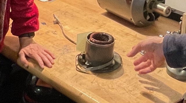
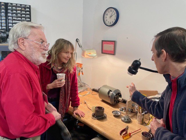
Frank King, his daughter Carla, and Ken Shirriff lamenting the poor thing’s end of life. :--))
|
- from Marc Verdiell
I went to investigate the cause of the odor and release of magic smoke in DE 729 #3.
I identified a suspect using my smell-o-meter, and confirmed it with my smoke-o-meter:
https://youtube.com/shorts/xxU5HFR2tIo
Looks like our vacuum pump transformed itself into a hookah.
I took it apart, and one of the motor windings is cooked, as you’d expect. It has many poles and appears potted, so it would be a real difficult task to re-wind it.
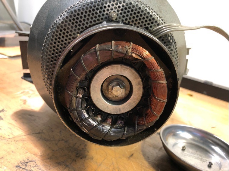
Surprisingly, vacuum pump itself was spotless – as in squeaky clean spotless – and ran smooth as butter.
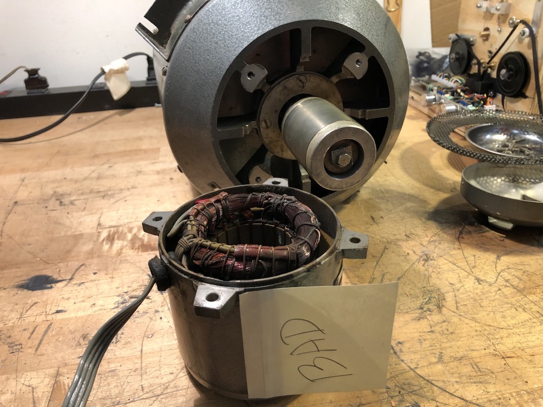
Then Ken reminded me that this is the pump that suffered a similar smoke incident 5 years ago. I had worked on it at the time, found it clogged by dust and debris, and its bearings were shot. I had replaced the bearings and cleaned it thoroughly – and apparently completely forgot about it. The windings must have been damaged in that previous incident and finally gave way.
It’s a 3-phase motor rated for European 220V/50Hz.

We probably don’t have another one of these, but Stan told me that the CT tapes had motors with ratings fairly close to that. Then Ken showed me on the schematics that Stan is right, at least some of the CT tapes should have 230V/60Hz vacuum pump motors in them (although I looked at CT#4, and it had a 208V motor of a different construction). The 230V would be close enough if we have one spare in Yosemite.
So, we should first try to see if we have a replacement in Yosemite before trying alternate revival methods. Robert is already working with Aurora to try arranging a visit.
So DE#3 will be out for a little while. It is turned off, and the terminator has been moved to DE#2, so DE can be demoed safely with tapes 1 and 2 in the meantime.
I also found CT#3 marked as out of service, but I could find nothing wrong with it, so I put it back in service. All 4 CT tapes appeared to behave.
Marc
|
-from John Howard
|
001-keypunch restoration 02-28-2024
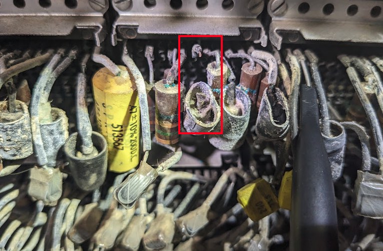
After cleaning the punch one of the die was very difficult to install and immediately jammed solidly. I was not able to clean out the die using my tools.
On Weds Fank and Arda modified a burnishing tool to it could be used to clean the surfaces of the die and stripper.
This has fixed the operation of the #3 die, however now the #9 punch is sticking. Both David and Mark had some excellent suggestions as to how to proceed.
This week I will modify the burnishing tool so it fits into the #9 hole better and see if that punch can be cleared. The next level of repair involves removal of the die-stripper pair, and I may start his process by learning on a verifier this week.
John
|
|
February 28 1401 demo
- from Scott Stauter
|
I acted as the lead and recruited Samuel Plainfield to be my operator. There were only 25 people for the 3:00 demo and then we had another 8 guests after the demo. I put recharged batteries in the audio-visual equipment, but #1 kept cutting in and out during the demo, and #2 would not work at all. This was not fun.
The keypunches and sorter worked fine. Maintenance was working on the CT 1402 so we used the DE 1401, 1402, and 1403. The DE 729s were offline, so we used all four CT 729s. The DE 1403 worked great, but the 1402 was giving reader checks, which we recovered from. Then it started giving reader stops, which we could not recover from.
Scott Stauter
|
Restoration Report for Feb. 27, 2024
- from Ken Shirriff
I went in today to check on the smoking 729 because the demo team wanted to use the 1401 today.
I found that DE Drive #3 had tripped circuit protector #6, which is the 208V protector for the vacuum pump and pressure blower. So the problem is probably with one of those motors. I left drive #3 powered off.
DE Drives #1 and #2 loaded successfully (which was a surprise since #1 had failed to load earlier). They didn't work from the TAU, probably because #3 was turned off, messing up termination. We can probably move the terminator to make these drives usable.
The DE 1402 crunched some cards for me and for the demo team, but then started working okay.
I also did some measurements on CT 1402 to figure out why it doesn't work. I got some interesting but confusing data.
At first, it was "chugging" (skipping clutch cycles) when doing an NPRO. (Note: I was not pressing CL #1 so this is wrong.) But then it started performing regular clutch cycles for NPRO, but the scope still showed problems.
This scope output shows NOT PROC FEED (yellow) and PROC FEED (cyan) while chugging. The strange thing is that it does a truncated NOT PROC FEED and PROC FEED (short pulses) which fail to clutch, and then it does a successful NOT PROC FEED (wider yellow pulses).
Three minutes later, without changing anything, the chugging went away. The yellow and cyan feed pulses are still very truncated, but slightly wider, enough to cause the clutch to trip. So even though it was operating correctly, there is an underlying problem. (I also noticed the truncated feed pulses in my measurements from last time.)
A few minutes later, the pulses were still wider. Overall, the PROC FEED pulses started at 7ms wide, then went to 11ms, and ended up around 20ms (compared to expected 17ms).
It is very strange that the pulses are truncated and also that the width changes without changing the frequency (i.e. the motor is running at the same speed). I think a relay must be switching to truncate the pulses because the cam timing should be steady. I think R11 #1 CL DELAY is the only one in the right place. (It shouldn't be active since there were no cards and I wasn't doing anything with CL #1.) But why the timing would change from minute to minute doesn't make sense. The armature of relay R11 seemed to be vibrating, so maybe it is tripping from the hold current?
The other thing I looked at was the LOAD failure on CT that I saw last time, but the behavior has changed.
Last time, LOAD didn't do anything. This time, LOAD causes one card to be fed into the throat and then a READ STOP occurs, repeatably. I took a bunch of measurements but I was unable to determine the cause of the READ STOP before I ran out of time. There was no obvious reason for a READ STOP; card motion was correct. But the 1402 would only do one clutch cycle and then READ STOP.
For the oscilloscope traces, I attached probes to resistors RD20 for NOT PROC FEED and RD27 for PROC FEED. I recommend this methodology when looking at feed issues because these signals are very informative and it is easy to probe these resistors. Getting relay state is harder. I soldered some wires onto a relay to view some signals, but I think we need a full relay extender to help diagnose this problem.
Ken
|
IBM 1401 demonstration Saturday 2/24/2024
- from Stephen Madsen
11:00 am
|
- from Duane Sand
Urgent: DE 1401 Smoking
|
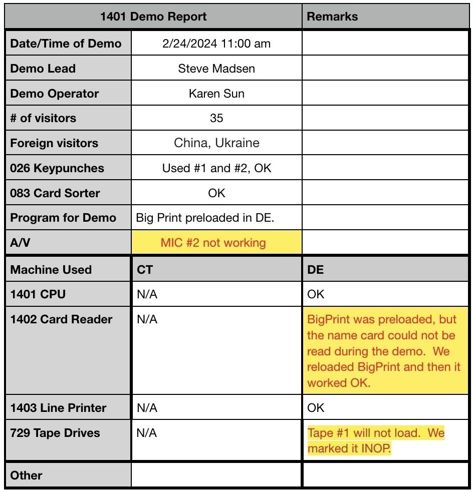
For the 1pm Saturday Feb 24 demo, we used DE, with CT powered down. Near the end of running BigPrint, the room filled with the smell of something burning. To minimize damage, we powered off DE and its 50hz power converter, and left A/C on. The scent reminded me of scorched fabric or paper insulation. The A/C cleared out most of the smell, so it was not coming from the A/C itself. Noses led it likely coming from DE's third, rightmost tape drive. It had been running normally earlier in the demo. Samuel shut off power to all 3 drives. We restored power to the rest of DE and successfully loaded and ran BigPrint, and the burning smell did not come back. So that confirms the smells came from some tape drive.
I think DE can safely run demos without tapes.
Lead Hara, operator Sand, backup op Samuel.
- from Larry Hara
- 1 PM Demo
Summary:
-
Burning odor post-demo traced to DE 729-3. Do not use until it has been examined.
- Demo went well but other problems afterwards
- BKM suggested on giving a demo if there is trepidation that the 1402 card reader won't work
- Audio needs attention
DE 729 Odor Problem: Post demo, we noticed a very strong odor (no visible smoke) like burnt papers that we traced to DE 729 #3; possibly SMS cards. Action taken: Immediately powered down DE. Samuel turned off the power to the 729s using the switch at the bottom right corner.
Need Restoration Team’s expertise to assess safety and operability. Much appreciated!
|
I’m not sure if there were plans for another 1401 training class or anyone to use DE before the Restoration Team has a chance to look at the problem on Wednesday 2/28.
As Duane says, DE could probably still be run without the 729 but I think that the Restoration Team should make that assessment. Your fellow 1401ers would appreciate that.
Larry
- from Ken Shirriff
There was a smoke event last year on DE 729 #3 when the tape take up motor windings burned up. (See the email thread "7/19/2023 CT1401/1402 Restoration Status ~"). The motor was replaced and I don't see any reason why the problem would happen again, but we should check this. One symptom was that DE 729 #3 kept tripping its circuit breakers CP9 and CP10.
Ken
- from Frank King
Yes, Jack there are 2 ways to turn off power to the tape drives.
one way: standing at the back of the drive there is a switch in the lower right hand corner, flip that switch
down.
second way: pull the right lower panel from the 1401. (Big flat cover} there are 2 cables, one large, one small, remove the small one. this will remove power to all the drives.
Frank
- from Larry Hara
Samuel switched the power off with the first method. We also carefully sniffed around the 729 and he thought the odor might be emanating from SMS cards. Samuel, want to comment?
|
|
IBM 1401 Restoration - Saturday 2/24/2024
from Robert Garner
|
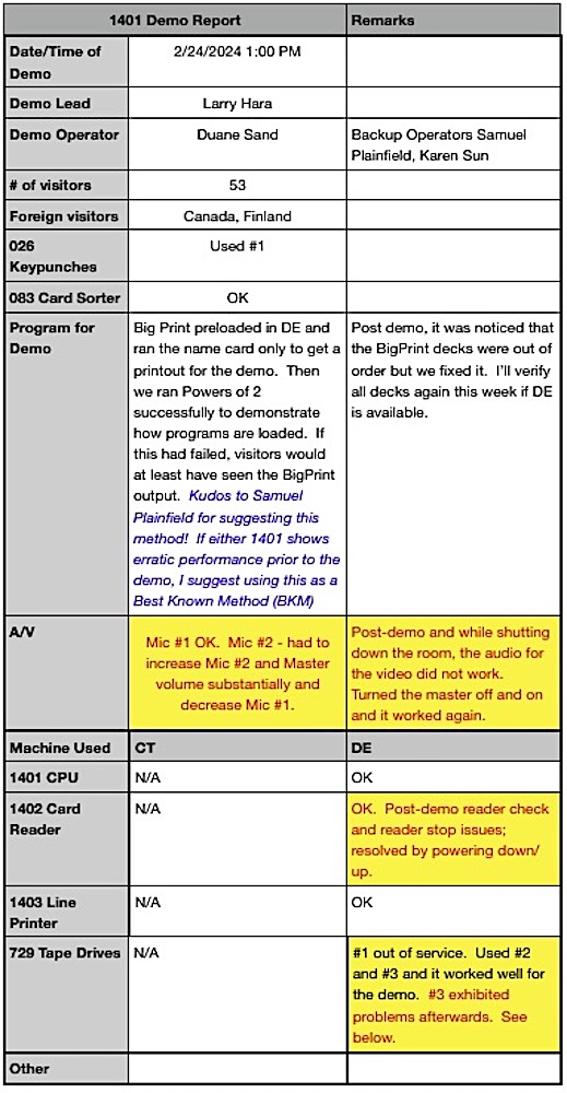
Marc, Dale,
Given that you (Marc) meticulously restocked one of our 1401-era CE tool briefcases (from several)…

… and you (Dale) brought yours in...
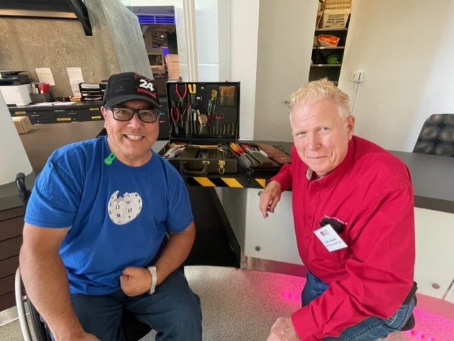
... I thought you two might appreciated this 1950s recruitment ad featuring an IBM tool bag:
Any guesses for the boxy item on the right-side pedestal? A tube tester?
Cheers,
— Robert
- from Marc Verdiell
Would that be a portable o’scope on the right?
Marc
Ohhh pretty tools! I would have signed up right away.
Marc
|
- from Ken Shirriff
|
Ken's current 1402 Schematics
I created a schematic that draws much of the 1402 relay logic in a sensible way (attached). This gave me some ideas on the 1402 problem so I went in today before the demo to look at CT 1402. I couldn't reproduce the card crunching or NPRO problems but now LOAD doesn't work.
Details:
I did NPROs with Card Lever 1 depressed. The CT 1402 had the same "chugging" behavior (skipping clutch cycles) as DE, so it seems to be working as expected.
I put a card into the throat and did an NPRO to reproduce the crunching problem. The card was crunched, but this was because there was a relay cover in the card path (!)
With the card path cleared, the card put into the throat was not crunched after NPRO, but it was slightly creased. The same behavior happens on DE so I think this is expected behavior if you put a card into the throat manually.
My theory for the chugging/crunching problem:
The relay logic tests that #1 CL DELAY and #2 CL match, i.e. that if a card was at CL #1 last cycle, it should be at CL #2 now. If there's a problem, instead of issuing a FEED, a READ STOP results. When CL #1 is held down manually for the test, there is a mismatch since the card reader expects to see a card at CL #2. It will trigger a READ STOP which is invisible since NPRO already creates a READ STOP. The NPRO will then start again the next clutch cycle. This is the cause of the "chugging" from missed clutch cycles. If there's a problem with #1 CL DELAY, the "chugging" will not happen. So I think CT had a problem with #1 CL DELAY but the problem went away when I tried to look at it.
I tried loading a program in online mode. LOAD caused the motor to start and a 1 in the 1401's opcode, but no clutch cycles so no card motion. The oscilloscope showed no PROC FEED or NOT PROC FEED signals issued. This is a bit strange because NPRO triggers these (although there may be differences with DE). So the signal must be getting lost in the relay logic, probably at relay 11 #1 CL DELAY. It's very curious that #1 CL DELAY turns up again. It seems that the lack of "chugging" resolved itself but turned into a new problem. Unfortunately, there's no easy way to probe this without a relay extender. But I think relay 11 may be the culprit.
Ken
|
- from John Howard
|
Keypunch restoration report 02-21-2024
Replacing the broken skip lever has enabled the escapement, however there is a jerky motion of the card after each hole is punched. This is caused by the punch retracting from the die too slowly after making a hole. I was not able to adjust the escapement and punch position to fix this problem.
The CE manual for 010 electric punch describes a method for oiling the punches. This procedure seemed to improve the situation somewhat.
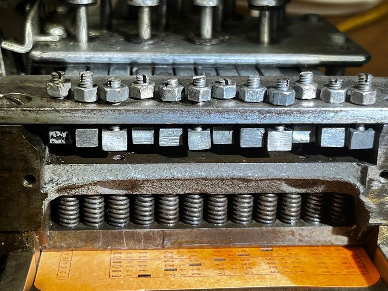
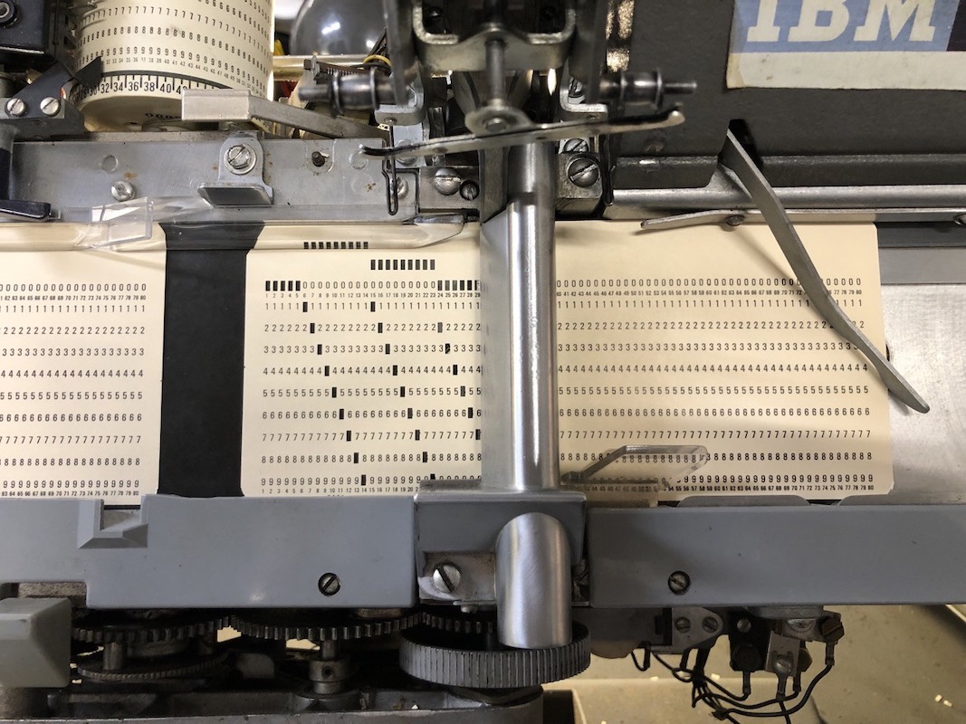
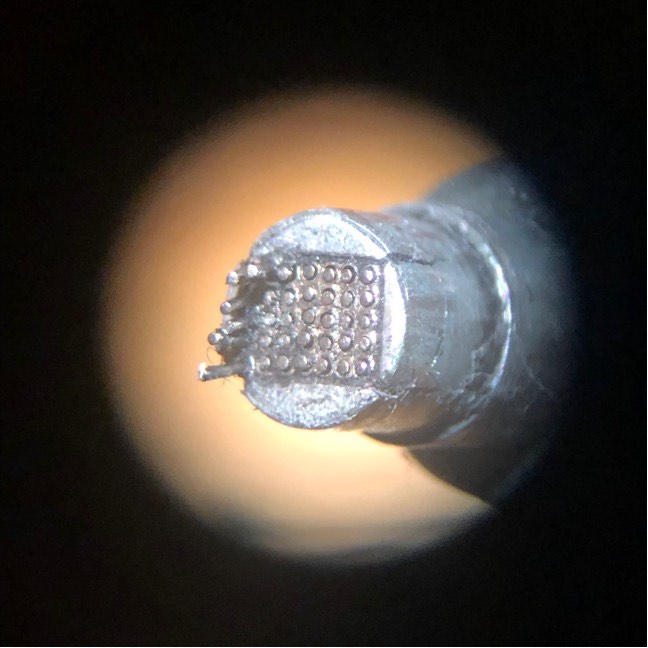
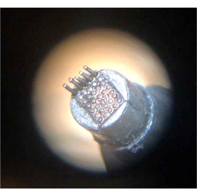
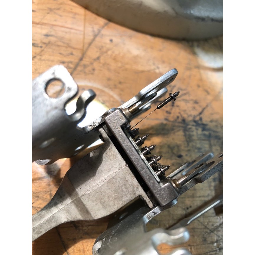
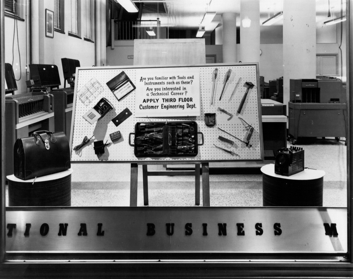
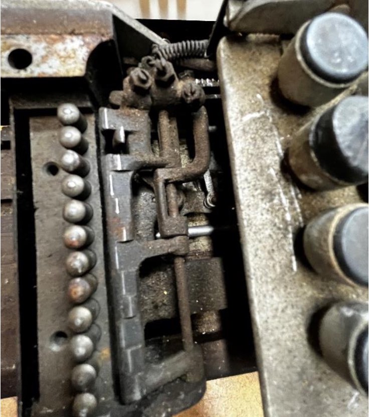
This is a photo of the 12 punches and springs. The screws along the top set the initial position of each punch. Each punch is retracted by a spring.
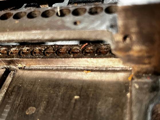
This is a photo with the springs and punches removed prior to cleaning on Wednesday. Years of accumulated oil and other debris.
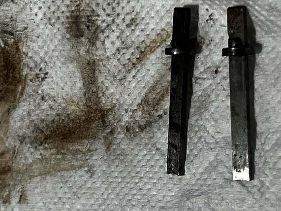
The punch on the right has been cleaned.
I concluded that the next step should be to clean the remaining punch mechanics using brake and clutch cleaner which I previously used on one of the verifiers.
John
|
- from Larry Hara
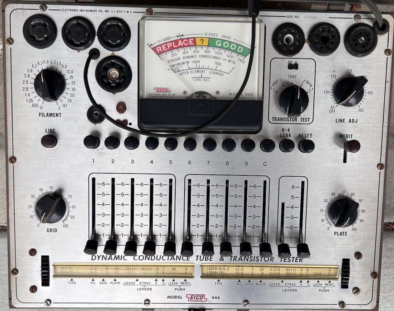
EICO model 666 Vacuum Tube Tester
|
Hello Restoration Team,
I have an EICO model 666 Vacuum Tube Tester as shown below. It powers up but I don't have any vacuum tubes that are known to be good to determine if it still works. Would you like it for your tools? Or if the Restoration Team doesn't need or want it, does any Volunteer want it?
Larry
- from Frank King
Larry, I would like to have it at the CHM even for a little while. The keypunches, sorter and even the 1402s have a couple of tubes to run the dynamic timer.
Frank
|
|
Feb 21 1401 demo
- from Scott Stauter
Today Tim Robinson, Pat Buder, and I gave two 1401 demonstrations - one at 3:00 and a second one when a group came in after our first demo. The first group had about 30 people and the second had 32 people. Our foreign visitors were from China, Estonia, and New Zealand.
The CT 1402 was being worked on, so we gave the demo on the DE machine. The keypunches worked fine and the sorter had a few cards that wouldn't go through the throat knife. It seemed a little tight. The DE 1402 got some reader checks, but after cycling the power off and back on, we could use it again for the second group. The three tape drives worked well and the printer performed flawlessly.
The audio equipment seemed to work today.
Scott Stauter
|
1401 Restoration, February 21
CT 1402 card munching:
from David Clementson
|
CT 1402 card munching:
We started the day by carefully examining the rat's nest of wiring behind the relay panel, focusing particularly on Relay #6 which was implicated by the QSpice model. It is potentially involved in the one-and-done clutch behavior we suspect is related to the card mangling problem. We did not see any problems specific to Relay 6, but did find one disconnected wire associated with the punch unit relays. After some probing with an ohmmeter, we found the proper destination for this wire and restored its connection. We also discovered that several of the punch relays had been improperly installed into their sockets, so we fixed that as well. None of these changes affected the reader's problem.
We next turned our attention to carefully examining the relays visually while they were operating. We noticed that the machine's behavior had changed from prior weeks in that it would single-cycle even if Card Lever 1 was not actuated. We eventually traced that to a bent contact in one of the relay sockets, a problem we likely introduced ourselves whild debugging. We fixed that and inspected all of the other reader relay sockets. We found no other problems. The machine was now exhibiting the same single-cycle behavior as we've seen for weeks, and it did not respond to any flexing of the relays or their wiring.
We did notice that when Relay 10 was manually picked by forcing its armature, the machine responded to CL1 correctly. So while we did not manage to find the root cause yet, it seems we are inching closer to finding the problem.
Next up is to use the observations we gathered this week to gain further insight using the QSpice model.
DC
|
DE 1402 "chugging"
from David Clementson
|
It chuggeth!
I added a qualification to the latch signal to play the role of the 1401's interaction. We believe the 1402 sends -T_NOT_PROC_FEED to the 1401 which returns -T_READ_CLUTCH with negligible delay. -T_READ_CLUTCH is an PNP emitter that provides the ground return path for the -20V clutch drive signal provided by the cams. Because both the cam drive and ground return signals are needed to energize the clutch solenoid, a logical AND is needed to simulate them. So I added an AND gate as shown here:
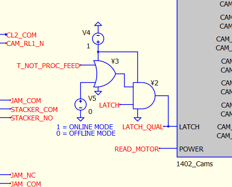
The OR gate just gives a way to override -T_NOT_PROC_FEED for offline mode.
The resulting simulation for an NPRO in Online mode with Sync off and Card Lever 1 active is shown here. Notice that the clutched shaft (red trace, second panel from bottom) halts for 120 degrees before latching again at the next opportunity. This is exactly the "chugging" that Ken observed on the DE machine.
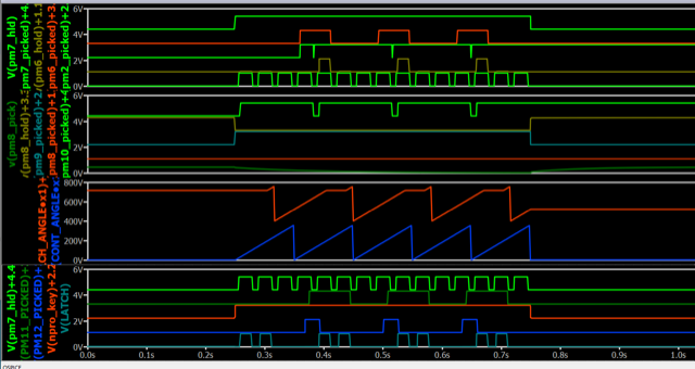
This is a pretty cool validation of the QSpice model, and is a good confirmation that DE is working as-designed, at least under these special conditions.
It will now be fun to try to break the model to simulate CT's misbehavior.
I will push these changes now.
DC
|
Restoration Activity 02/21/24
from Tom Szolyga
|
Today I investigated the flash drives that were in a plastic bag in the work shop. The drives were Stan’s library of 1401 items. There are files for the HW and SW 1401 projects he worked on as well as many historical pictures and documents. I decided to save all the content for “Future Generations of Volunteers”. ;-) I am copying them to my 1401 content nVME flash drive and to the 1401 cloud storage under the CHM umbrella. This will preserve them.
Best regards,
Tom
|
- from Marc Verdiell
I turned my attention to the 026 that had be languishing in the workshop for months. The bad noise was dealt with by tensioning the belt, and a new ribbon was installed thanks to the awesome re-inked ribbons (thanks Dave and all!).
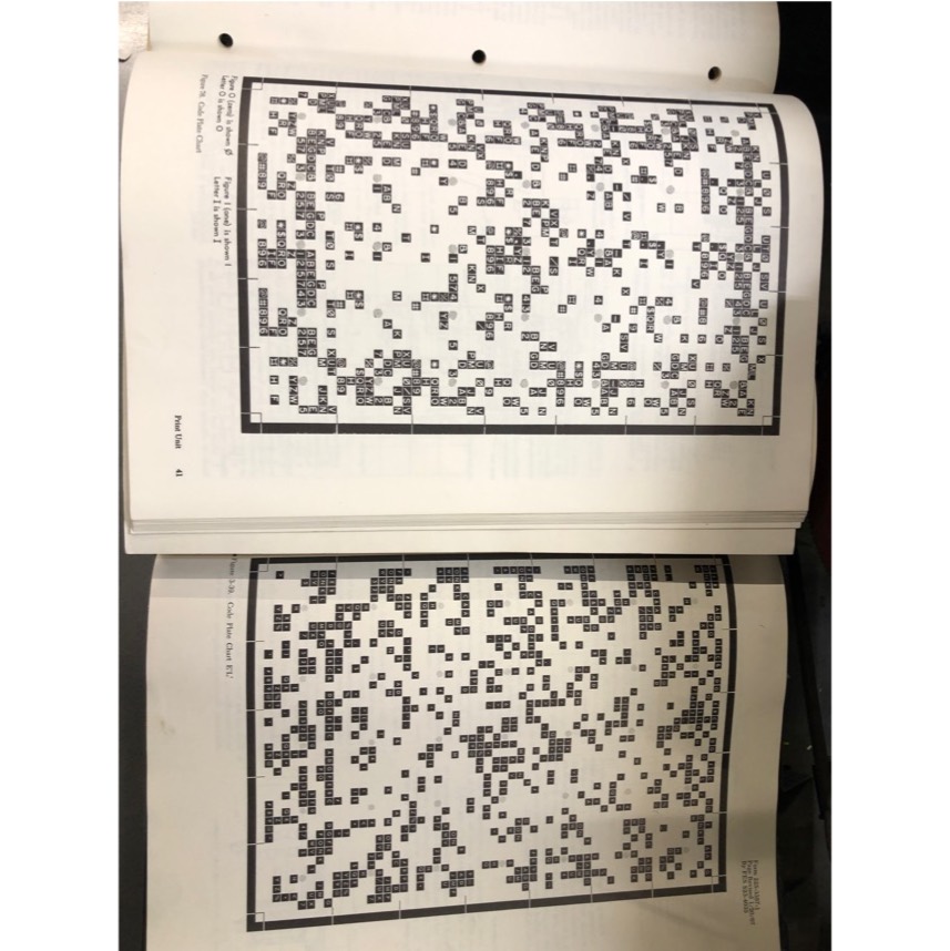
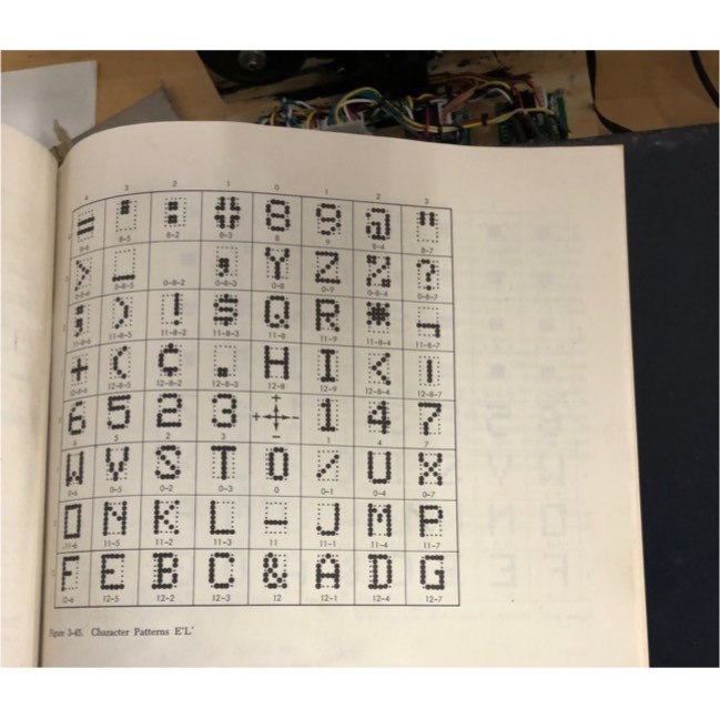
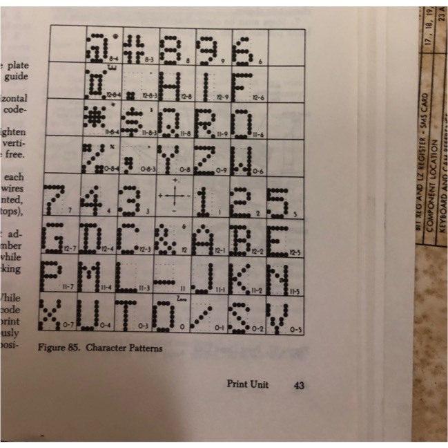
At first it printed complete gibberish
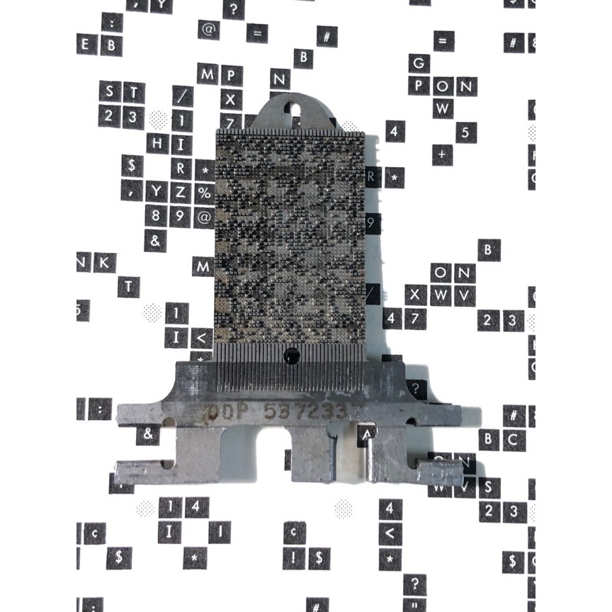
Which got me thinking that the character plate was not straight. It wasn’t. The control linkage had been reassembled slightly out of straight. After a quick straightening, it worked as it should, but printing the wrong chars, because the plate is out of alignment.
Usually it’s a simple matter of finding out which way it is off. It was actually perfectly aligned on vertical. But on horizontal it was off by random amounts and directions depending on the character. But not quite completely random, always by an integer multiple of character positions. Which should be mechanically impossible.
Unless the “digital” pegs in the horizontal displacement control had been somehow swapped around.
Ken compiled the displacement of each character and confirmed that was the case. There is not a single pin in the correct place.
The peg assembly is way deep in the bowels of the machine, and not a part you ever need to disassemble either, so I’m not sure what happened. Over abundance of restoration enthusiasm is my guess :--))
Anyhow, I tried to remove the assembly with Frank but was unsuccessful. We’ll have to get it out of there next time, put the pins in the correct order, and realign the printing plate. This should be new and entertaining!
Marc
|
|
IBM 1401 Demonstration 2/17/24,
from Steve Madsen
- 1:00 pm
|
- 3:00 pm
|
Restoration Report for Feb. 17, 2024
from David Clementson
|
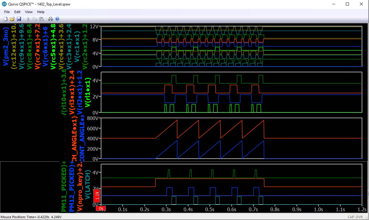
The QSpice model of the 1402 card feed relay logic is starting to bear fruit. The simulation shown below shows that PM Relay #11 is indeed supposed to be picking once per clutch cycle during an NPRO with Card Lever 1 constantly actuated, while it is not picking during an NPRO if Card Lever 1 is not actuated. This is the observed behavior of the DE machine, and was the observed behavior of the CT machine before it started eating cards. We believe CT's card mangling problem is related to this behavior somehow. Further, we think the root cause is a loose wire somewhere in the relay frame, since manipulating the wiring harness just right restores the Relay #11 cycling. The plot below shows the cycling of Relay #11 (top trace of the bottom panel) during NPRO + CL1, but the cycling is absent when the simulation is re-run with NPRO but without CL1 (not shown but take my word for it).
The middle sawtooth waveforms represent the shaft angles of the clutch and continuous shafts. The upper two panels show the continuous and clutched cams respectively. The time scale is set to 600 cards/minute.
@MarkL: I added the RC delay components for PM8 per our conversation. This should make the model 100% complete, albeit without any model for the actual cards themselves. We would need to model the cards as they go through the machine in order to get to the next level of operation. I'm pretty sure we could model the card deck as an array of capacitors whose voltages correspond to their position along the card path. The caps would be charged by switched constant-current sources whose current represents the roller velocity. Their switching, representing which particular roller they are currently influenced by, would be governed by their machine position via a network of voltage comparators. The one thing I don't have a handle on is how to model the cards' stacking. Each card would need a second state variable representing its position within the deck. Only the bottom card would be allowed to leave the hopper, etc.. Ideas?
I pushed the commit to GitHub. Anyone following along at home is welcome to download and install QSpice (Windows only, sorry), then clone the repo from GitHub. If you search "IBM-1402-QSpice-Model" on GitHub you'll find it.
DC
|
Demonstrations - February 14, 2024
from Larry Hara - Re: CHM 1401 Demo Card Deck refresh
|
Thanks Jack for a great write-up! I especially like the protocols which I think we should include in the manual and keep or post it somewhere discreet but near the 1401. Maybe in a binder on the demo cart along with other operator instructions? I'm not sure about the other Operators, but I sometimes find it reassuring to refer to the Operator's Manual to make sure I'm not forgetting something.
I drafted an email yesterday to summarize the work that Jack and have revised it to include latest updates from today:
Following up to my email and inputs from several of you, Jack and I went through ALL BigPrint decks on 2/13/24 and good news: all BigPrint decks have been verified using VOBJ and show no card mismatches. Here are some of the findings that got us to that point:
- some of the cards were slightly bent or warped on the edge. We duplicated the cards and used the "good" cards not the "name" cards.
- there were several cards made at some point in history with "name cards," but we did not encounter issues with them.
- Two of the decks had previously encountered reader stops on card 94 on Deck #3 and 87 on Deck #4. However, if you use slight finger pressure on the card weights, you can resume loading the un-read cards successfully. Obviously that's not a good way to operate, so the weight cards may need a very small amount of weight added. VOBJ confirmed that Decks #3 and #4 matched all the other decks.
- The location of the holes on suspect cards were good, as confirmed by the metal template. The characters were exactly where it should be. Today, Pat Buder pointed out that on some cards, the printing of the numbers on the card may be slightly offset, yet the holes are where they should be.
- We don't know why I had encountered different card mismatches when I previously ran the same deck consecutively
I'll check the decks again next week to see how they are faring.
Larry
|
from Samuel Plainfield
|
To avoid mixing up the deck (particularly when short on time during demos), I like to follow this foolproof protocol to be 100% sure that everything stays in order:
Reader Check
- Remove the remaining cards from the joggler and set aside face-up. The last card in the stacker is the card that caused the check.
- Close the now-empty joggler gate and hit NON-PROC.
- Two cards will descend into the stacker.
- Remove all cards from the stacker.
- Take the last three cards and put them on top of the cards you set aside in step 1.
- Place the remaining card deck you set aside from the joggler back into the joggler to press START (not LOAD) to resume the reading of the deck. The card that caused the check will be re-read and hopefully not cause a check again ... and the deck will finish loading.
This will be very straightforward once demonstrated. The above method helps keep both "sides" of the deck distinct, hopefully systematically reducing confusion about which card should go where. :)
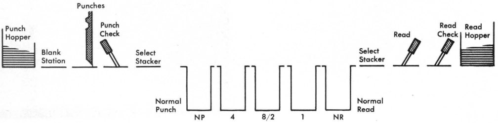
It's also perhaps important that we make sure our new Operators be familiar with the terminology. NR stands for Normal Read. IBM has a bunch of unique terminology they use. The stacker, by default, places all cards into the NR stack unless indicated otherwise by software control.
The 1402 is a remarkable device.
~Samuel Plainfield
|
|
Restoration Report for Feb. 14, 2024
Note: No reports for Feb. 7th, All of CHM rented out
From David Clementson
|
CT 1402 Card Munching:
We resumed where we left off but scoping Relay #2 (Card Lever 1) pick and hold coils and found that they were showing the "stateful" behavior where the relay would not drop at the end of an NPRO cycle with CL1 active. Relay 12 was similarly not dropping, showing a single pulse after the NPRO key was pushed with CL1 active, then no further activity until the third press of the NPRO key.
We also noticed that Relay 11 (CL 1 Delay) was also exhibiting this behavior, picking once and only once. This can be observed by watching the armature of Relays 11 and 12. However we observed that Relay 11 would occasionally pick repeatedly and the clutch would cycle repeatedly if we manipulated the wire bundle behind the relay frame in just the right way. So it looks like we have an intermittent connection or a shorted wire somewhere in the relay frame wiring. We tried reseating the wires associated with Relay 12 but with no positive result. So we will need to try to run down this bad connection by trying to pinpoint the exact location within the relay wire bundle where manipulation is most effective. When the wire is in the correct position, relays 11 and 12 should both pick repeatedly when an NPRO cycle is run with CL 1 active.
1402 QSpice model:
Mark L. an dI have the
1402's QSpice Model about 95% complete. Yet to do is add the RC delays associated with the pick and hold coils of PM #8. We also need to check that we have correctly modeled the unit in "Offline Mode" (6PDT switch "CT" shown in the engaged position), otherwise we would need a model of the 1401 to plug in to! Then it would be ideal to do a formal "design review" possibly together in a conference room at the museum. Finally, we can check the model's operation against the operations described in the "Read Feed Circuits" section (PDF page 24) of the
CE Manual.
Finally, just after the Demo, I received a call that my wife has tested positive for Covid-19. I immediately masked up and tested as soon as I got home. My test result was negative and I am not feeling any symptoms. Hopefully, I did not bring the virus to the museum, but please be advised that it is in the environment.
DC
|
from Marc Verdiell
I worked on the tape emulator, and it’s partially back up from the dead. The computer boots (thanks David for the recapping), it has all the colors on the screen (it was a bad SVGA cable), and the emulation software starts up normally. In testing from the TAU on DE, I was only able to get emulated tapes 2, 4, and 6 to respond. Emulated tapes 1, 3, and 5 did not work. I’m pretty sure that’s because the selection signal for these tapes does not make it through for some reason (cable problem, or some fault in the emulator box). To be investigated and fixed next time.
Marc
|
from Ken Shirriff
|
My report: investigated using a Hall-effect sensor to determine relay status. Did some 1402 measurements. Tried unsuccessfully to understand how relay 12 (feed control) and relay 13 (stop control) interact.
Ken
|
from John Howard
|
IBM 1401 demonstration 2/10/2024
from Jack Ghiselli - 11:00 am
Powers-of-Two demo deck completely loaded, to Last Card, in CT1402 No card crunching.
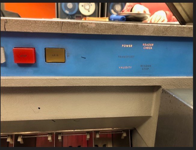
CT1402 Front Panel shows Reader Check and Validity Errors. I/O Check Stop was OFF, so load continued to Last Card.
CT1401 Front Panel is nuts. Lots of error lights and random displays. CHECK RESET came on with 1402 Validity error.
The demo deck must have loaded enough good data for columns 40-71 to execute, but the executable object program in
columns 1-39 probably was garbage. No time to investigate further. We just quit using CT and went to DE.
Jack Ghiselli
jghiselli@sbcglobal.net mobile 1-408-839-1051
|
from Stephen Madsen - 1:00 pm
|
Restoration, Feb 6, 2024
from Robert Garner
|
Larry,
I was also wondering: Was the DE1401 panel displaying any other red lights besides READER?
(When you have this failure in future, could you please snap a photo of the panel?)
> Reader stop and read check issues sometimes resolved by powering off/on but later nothing could be run.
Sam and I have also seen that behavior. After about four attempts, the DE 1401 eventually complied.
Thanks,
— Robert
p.s. Hopefully what you saw wasn’t the cacophony of red lights we were getting earlier (now hopefully fixed by replacing the bad CQZV card):
We’ve still occasionally seen this light display:
|
from David Clementson
|
Great! Here's an update.
I didn't realize that the Duo relays in our unit are 4PDT instead of DPDT, so I added two extra sets of contacts to its model and recreated the hierarchy symbol. And instead of just using the Duo relay symbol for the operator switches (NPRO, etc.) I made a proper DPDT module for them. I also found that the Hold coil for Relay #4 (READ STOP) is not ground-referenced like the others. Fortunately, it is referenced to the -20 volt power supply (logic "1" or +1 volt in the model) , effectively inverting its behavior. So I just added an inverter to drive that signal. I plan on working on it more today and will try to push an update to GitHub tonight. My first goal is to get the main motor to turn on when NPRO is pressed.
DC
|
from Ken Shirriff
(about the intermittent CQZV card)
|
Very interesting, another bad inductor! Good work tracking this down. It's still unclear why the card worked sometimes (at home
and in the SMS extender) but not when plugged in. Maybe an intermittent contact in the inductor?
Ken
|
from Robert Garner
|
Ken,
> Maybe an intermittent contact in the inductor?
Definitely looks that way.
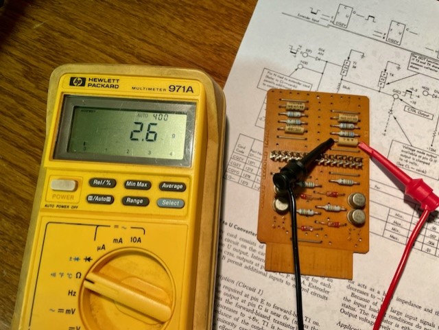
Putting it on the I-V curve tracer and gently rocking it shows the current chaotically jumping between
a near open circuit (perhaps around 400k ohms) and a doggy attempt at 2.6 ohms,
per this 6-second video:
Entropy: +1
Cheers,
— Robert
p.s. One could dissolve its encapsulate to see frail or corroded wires inside?
|
from John Howard
|
Robert,
The type number plate from our punch is 001-10003-JPN
The parts catalog title is 01-51 Mechanical Punch & Verifier.
The recent document from Peter answers the question about the historic use of the X key! It can function as a tab. The mechanical logic makes sense now, there is a mechanical OR function at the escapement pawl. The X key OR the Release key can activate the escapement. All our machines use a non-skip bar which performs no added function, consumes a significant number of unused parts, and adds another mechanical escapement adjustment.
HUGE thanks to Peter.
John
|
from Robert Garner
|
Good to hear John/IBM’s 1936 document was helpful (re: the X key).
Although the X-key is not present in our “001,” it sounds like you see mechanics in our unit that support it?
(i.e., “The mechanical logic makes sense now, there is a mechanical OR function at the escapement pawl.”)
The parts catalog title is 01-51 Mechanical Punch & Verifier.
The 1987 listing of all IBM products appears to reclassify it as “0051," consistent with their bone-dry 4-digit nomenclature.
The listing shows introduction sometime in 1910 and also shows several of its “Verifier” siblings, the 0059 introduced as last as 1966!
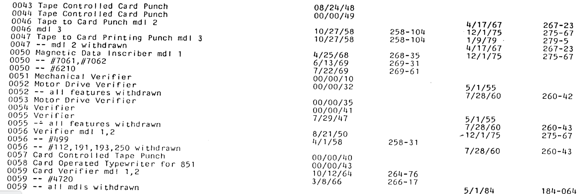
Perhaps someone in IBM product marketing bucked the naming rules with the two-part "01-51" designation?
(at least it’s 4 digits. There is no “0151” in the listing.)
The “001" was sanctified as a 4-digit part number with another leading 0, as in “0001”, and was manufactured up until 1953!
The type number plate from our punch is 001-10003-JPN
Ah, good to know it’s an actual 001.
I presume "10003-JPN” implies serial #10,003 and that it was manufactured in Japan (JPN was Japan's ISO abbreviation)?
Cheers,
— Robert
|
|
Restoration, Feb 5, 2024
from David Clementson
|
Hi Mark: ( Loomis )
I have added the cams and clutch, PM and Duo relays, and the Card Lever switches. I also put in a few connection nets. I think this should be enough for the basic modeling of the card transport. Now we have the real work of adding all of the interconnection wires...
If you want to play with it, you can download it from GitHub.
Unzip everything into one folder, then open the top level schematic. Simulate it, then open the top level plot configuration file and you should see a result similar to the one I posted yesterday.
BTW, if you look inside the underlying relay models, you'll see that each switch terminal has a 10Meg pull-down resistor. This is to suppress floating net warnings, plus it gives every node a definitive voltage. Everything else is pretty self-explanatory.
DC
|
from Robert Garner
|
Ken,
I figured out why the “bad" CQZV card is actually bad (causing the DE1401 to occasionally seize) —it’s a faulty inductor.
We were led down the garden path positing our normally dodgy transistors and diodes.
And it’s not a bad ohmic contact on the card edge connector or a backplane socket pin.
Here the device tester couldn’t grok what the bad inductor actually is, showing a question mark (?), versus a good 50-microHenry (.05 mH) inductor:
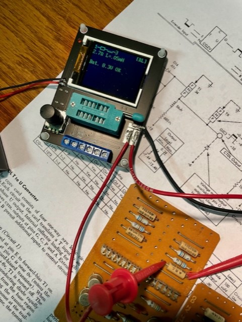
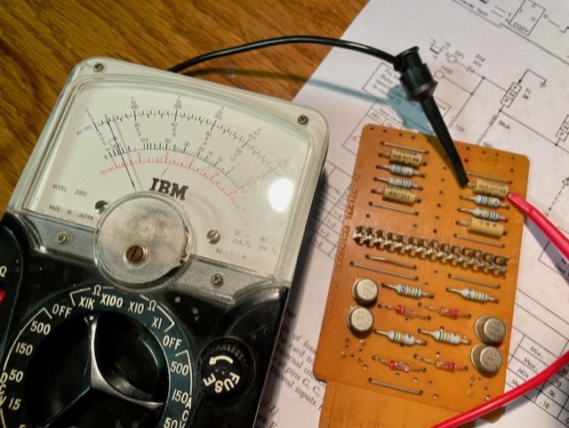
My digital multimeter could not settle on its resistance, but my analog VOM measured about 400 kOhms (vs. 2.6 ohms for a good one):
Background story: After the I-V curve tracing I did last week (which showed all good transistors),
this week I brought home a good CQZV card to compare against and a backplane socket receptacle
to see if a sketchy card edge pad or possibly a backplane socket interaction might be the culprit.
Lowering the input voltage all the way down to about 0.086 V was the only way to get an output
near -6V to -8V; i.e., what you saw last Wednesday in the DE 1401. This was true for both the good and bad cards.
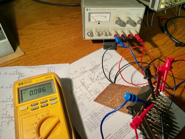
Since such a low input current caused the low output voltage, that got me thinking that perhaps one of the
discretes in the collector pull-up path (resistor or inductor) could also be limiting the output current
(and thus the low voltage). That led me to testing the resistor and inductor. Bingo.

Whew,
— Robert
p.s. This might make one fret about the hundreds of inductors in our 3000 SMS cards.
This is not the first time we’ve had an inductor fail on us:
https://ibm-1401.info/Sched2005November.html
https://ibm-1401.info/TimsInCircuit.html
While it's all setup, I'll measure the output speedup the inductor is purported to have on the rising output signal.
|
|
Demonstration: Saturday 2/04/2024
from Karen Sun - 11 AM Session
|
Larry Hara and I gave a demo to 45 visitors including those who checked in the lab room before and after the demo. The foreign visitors were from Germany, China and India.
I arrived early to test the CT1401 and DE1401. CT1401 didn't crunch cards but just gave me validity checks and reader stop checks, yet it still didn't load the deck so I turned it off. Before the demo I tested the DE1401 to successfully run the BigPrint after trying a second deck. I planned to preload the program during the demo so that we wouldn't have any issues.
It turned out Larry and I didn't communicate about how we would like to run the program before the demo. He re-ran the BigPrint again during the demo and the deck loaded but it didn't print out anything. Larry told me he would like to take a look and let me continue the demo. Lesson learned that I shall tell my demonstrator to join me for the rest of the demo instead of digging into debugging the deck himself. While I kept passing over the props and collecting them back by myself with Larry running the deck several times beside me, the audience irritatedly switched their attention to the live debugging instead of the demo. I had to pause and check with him about the progress. Then I firmly asked him to join me to demo the CPU together and we could give the deck a look after the demo. (After the demo I communicated it with Larry and he agreed that it was not wise to keep debugging while the demo was on as well as we shall preload the deck if it worked at first before the demo:-)
After the demo Larry figured there was no issue with the deck but the date card was bad, mostly frilled. He made a new one and we were able to do some printouts for our visitors staying after the demo. I was surprised how soon a newly typed date card could be broken just after a second run, the first run was done by me before the demo for testing. Lesson learned again that we could prepare two same date cards if they are so easy to be frilled and not be able to be read through by 1401.
The sorter worked fine and all the three keypunches worked well. The tape drive worked fine. Mic #1 had some intermittent cutout.
|
from Larry Hara - 1:00 PM Session
Summary
- DE 1402 not working well. Restoration Team: can you please help? We'd appreciate it.
- BigPrint decks need attention
Question/Issue?
Found 4 vials of core ferrite in the demo box. Didn't we have 5?
I did a few tests on Saturday, 2/3 to identify the source of issues with the BigPrint Decks and/or DE 1402.
Summary
- There are 3 good BigPrint decks that can be used for demos
- VOBJ shows inconsistent results on suspect decks
- 2 of the BigPrint decks encounter reader stop issues for reasons TBD
Current Status
The decks labeled as Deck #1, #2, and "Frank King" seem to be usable. Use caution with Deck #1 since the edges appear worn. Deck #3 encounters a reader stop after card 94, 95. Deck #4 stops loading on card #87 (even after duplicating) as previously reported by Jack
Method
I ran VOBJ using the "Frank King" deck as the known good deck since the program ran successfully and consistently.
Results
The table below shows that on card 50, there are card mismatch errors although the code matches exactly. However the Frank King deck can still be run successfully. Card mismatches occur on other cards in Deck #2 but the specific card that is flagged as a mismatch is neither repeatable nor consistent, as evidenced by repeated trials on Deck #2. The mismatches appear within the first 20 columns.
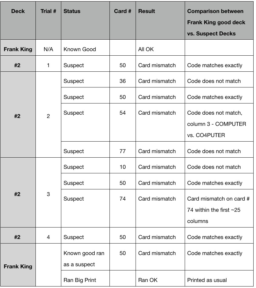
See attached PDF for pictures of the printout from VOBJ.
Unresolved questions: Why does:
- Card #50 show a mismatch when the code is exactly the same between 2 different decks?
- BigPrint run successfully despite #1 above?
- The VOBJ report show different card mismatches when deck #2 is run repeatedly?
- The mismatch seems to occur within the first 20 columns of the deck. Could this be indicative of an area of the card reader that might have a hardware issue?
Next Steps
I plan to run VOBJ but if I continue to get similar results, is it possible to get a clean fresh copy of BigPrint on good cardstock? Since the card punches on the 1402's aren't working, is there a golden copy stashed away somewhere that I could duplicate manually and use it as a secondary standard?
I'd appreciate your collective intelligence and suggestions.
Larry
|
from Robert Garner
|
Larry,
I wanted to confirm that, for program decks (e.g, BigPrint), you're not using the new blank “Name” punched cards.
The Name cards are not made with genuine IBM-spec'd paper stock, so we should limit them to onetime-to-low usage.
To me, the newly manufactured cards (from TimeCardsUSA/SignalSystems, the last vendor standing*) feel smoother/slipperier
than the period/genuine cards. What do you think?
A single box of Name cards resides in the A/V closet and they populate the 026 keypunches.
The remainder (of the last order) are stored in several drawers in the back room, on the right side,
where they’re rigidly compressed to reduce bowing/bending.
The period Vintage cards (for program decks or other high usages) are on the left side, per this photo:
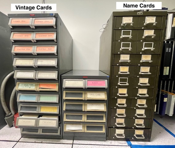
We have a stash of about 200,000 Vintage cards still in the Yosemite warehouse.
Cheers,
— Robert
p.s. Also note this earlier email from Frank King back when we were adjusting the card picker knives:
On Aug 7, 2023, at 1:05 PM, Frank King wrote:
We added the extra weights on the card weights to help flatten the warped cards. Any stored cards should be stored in drawers/metal boxes with compression locks, so it will help keep the cards straight. But we will be fighting this problem until the end of time.
We might need to apply some engineering to the card weights. i.e. the springs on the bottom and the amount of weight and where it is placed on top of the card weight. We did the best we could over the years but some of the things we did was without much engineering applied. There is no doubt the feed knives are worn some, even if they may not be the source of the problem. The card weights we are using were designed to pass through a file feed smoothly and if necessary to separate cards falling on top of them, i.e the next program.
Thanks for all the work you guys are doing to solve these problems.
Frank King
|
|
Restoration 2/04/2024
from Mark Loomis
|
I did a little bit of digging yesterday and arrived at a similar conclusion - most of the recommendations I saw were to use LTSpice for simulation relay logic. I don't have the 1402 schematics in front of me, so I wasn't sure how important it is to closely model the circuit vs. abstracting the behavior into a pure digital model in Verilog. Staying closer to the circuit has the advantage of being able to match simulation output to something we can measure on an oscilloscope; the Verilog model would be more flexible for creating test scenarios to understand the behavior. In any case, the QSpice path looks interesting so definitely bug me if you need Verilog help, or C++ for that matter. I'll have QSpice installed on one of my Windoze computers soon, so we could try collaborating on it also. Are scans of the 1402 schematics online somewhere?
|
from David Bennet
|
When I placed the first order for brushes for the 1401 tape drives from Helwig Carbon Products,
see document here
they created a part number for them, using a sketch and a description of the application, which I gave them. Apparently the resulting brushes were satisfactory because I was asked to order some more. Making brushes for motors, etc is Helwig's business so when I found out that they had created a part number for us at the time of the first order, I simply ordered another batch according to their part number which was specific for us.
If someone would like to delve into the characteristics of the material that they used for our part number I will be glad to turn over the role of interface to to Helwig Carbon Products to that person. Personally, I don't know enough about making carbon brushes to carry on a dialog with them about their business. Let me know if you would like contact info.
If I were interested in following up on this, I would want to know if the brushes that seemed to be wearing excessively were really the Helwig or the home made ones.
Dave Bennet
|
from Marc Verdiell
The vendor should have standard hardness materials to choose from. You balance hardness with friction and contact resistance basically. I don’t think friction or contact resistance is very critical here. We should just ask them what materials they offer and get one or two rungs higher on hardness. Or ask the vendor for advice - they should know.
Marc
Oh it’s that old? That was one of my first heroic repair. Time flies by! Maybe it’s normal wear then. Asking if they have harder material, or something they recommend for riding on copper is probably worth it.
Marc
|
from John Howard
from John Howard
John,
Thanks for the report!
Sounds like you’re making excellent progress on the release mechanism and it’s great to hear that it’s punching again. :))
Is this photo of the 001 release mechanism or from one of the verifiers?
>> Recently a parts catalog for an IBM 001 keypunch machine was located
Did you mean to type “parts catalog for an IBM 010 keypunch”?
Thanks,
— Robert
|
|
Restoration 2/03/2024
from David Clementson
|
Hi Mark:
So I've been experimenting with logic simulators and have some results.
After watching Marc's video about LogiSim, I downloaded it and gave it a try with the goal of simulating the clutch & cam system. I set up a pair of counters representing the clutch and unclutched shaft angles (in 1 degree steps, modulo 360), and got them to synchronize to each other in response to a clutch latch signal. I was also able to model all of the clutched and unclutched cams. I only crashed the simulator four times! But then I realized that the software is totally incapable of analyzing its own simulation results: its "oscilloscope" has a memory depth of only 30 samples, and its "chronogram" cannot zoom at all, making inspection of multiple 360 degree machine cycles virtually impossible. And it doesn't store its chronogram parameters, so you have to set them up from scratch each session. It is a real pain!
So then I looked at QSpice. QSpice is the next generation of analog simulators from the guy who wrote LTSpice, so I have high confidence in its accuracy and stability. It has some unique features that might make modeling the 1402 (or at least parts of it) possible:
- It allows circuit modules to be written in both Verilog and C++. This will make the cam generation really easy.
- It has a voltage-controlled switch primitive, which will make the modeling of our dual-coil relays easy. This gets around a major stumbling block for using a traditional digital simulator for relay logic, since we often can't tell which direction the "logic" flows across relay contacts. With actual switches, we don't need to know.
- It supports hierarchical design, and seems quite at home modeling digital circuitry. Many of its example files model complex ICs (switching voltage regulators, for example) that have a mixture of analog and digital circuitry inside.
So I am currently working on a clutch/cam module with the guts written in Verilog. I am VERY rusty on Verilog so I may need to lean on your expertise if that is okay with you. I'm envisioning a Verilog block that accepts an input clock (one tick per degree of machine rotation), a "power" input that corresponds to the AC motor that drives the unclutched rollers, and a clutch latch input that trips the clutch at the proper angle and activates the clutched cams. This module will also have boolean outputs for each of the cams. Those booleans will in turn drive switch primitives that will get interconnected to the relays.
I'll post results as I make progress. But I may need to bug you in case I get stuck.
Cheers!
DC
|
from Mark Loomis
|
I did a little bit of digging yesterday and arrived at a similar conclusion - most of the recommendations I saw were to use LTSpice for simulation relay logic. I don't have the 1402 schematics in front of me, so I wasn't sure how important it is to closely model the circuit vs. abstracting the behavior into a pure digital model in Verilog. Staying closer to the circuit has the advantage of being able to match simulation output to something we can measure on an oscilloscope; the Verilog model would be more flexible for creating test scenarios to understand the behavior. In any case, the QSpice path looks interesting so definitely bug me if you need Verilog help, or C++ for that matter. I'll have QSpice installed on one of my Windoze computers soon, so we could try collaborating on it also. Are scans of the 1402 schematics online somewhere?
|
from David Clementson
|
Hi Mark:
The trouble with making an abstracted behavioral model of the 1402 is that we (or at least I) don't actually understand how it is supposed to behave. So for me, the purpose of making a close model is to help me understand how the thing is supposed to work. And to be clear, the model I'm working on is not the complete machine, but rather only the card handling logic on the reader side. That's because that is where the machine is currently having problems.
I made progress on a QSpice model yesterday. I have a Verilog module (attached) that models the continuous and clutched cams plus the Solar Cell. Please have a look at the file to see if I have made any rookie blunders. The plot below shows the simulation results (note that I have added DC offsets to the signal plot expressions to separate them vertically from each other in the display.) The two sawtooth plots represent the angles (0 to 360 degrees) of the continuous and clutched shafts. You can see when the clutch latch signal at the bottom becomes true, the clutch latches at the correct 315 degree location. The clutch shaft turns and the clutched cams operate. If the continuous shaft gets to 315 degrees with the clutch latch signal inactive, the clutched shaft stops and stays at 315 degrees. The cam angles should be correct, but they could use a good checking.
Next up is the modeling of the PM relays with their pick and hold coils. I believe that all of the 1402's relay coils are ground-referenced, so I can use simple logic to represent their coil drive signals. If I encounter a relay coil that is not ground referenced, I'll need to figure out how to "float" the ground terminal of its logic drive.
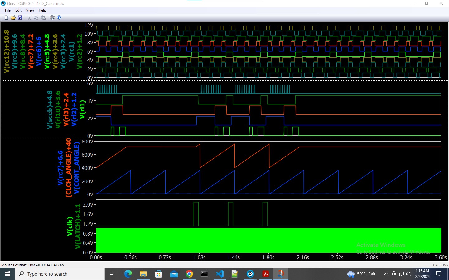
DC
|
|
Demo Report 1/31/2024
- from Samuel Plainfield
|
The 1/31/2024 3pm demo went just fine. I was lead and Scott Stauder was Operator for the day. Duane Sand came in to help out as well.
Keypunches were all fantastic. Microphones worked well, although maybe it's just me, but it seems that there is distortion and drop-outs with Mic #1. I tried to reduce the volume, but I can't seem to get the microphone itself to move further back so as to avoid the distortion/clipping effect.
Tape drives on DE all worked well. Sorter worked great. It just so happened that BigPrint wasn't pre-loaded and it worked well, as did Powers of Two.
Museum attendance was light, so we only had about 35 guests with 20 or so before and after. David Hoyt came in last-minute as we were shutting down with a very interested group of 8 or so people. I was able to provide them with a condensed demo which they were absolutely thrilled about.
Robert and I were cleaning up later on and there was a ton of paper I tossed out/recycled. We sure do go through a lot of paper!
That's all for now folks,
~Samuel Plainfield
|
|
Restoration Reports 1/31/2024
- from John Howard
|
CT 1402 Relays
David noted that the schematics for the reader punch device call out two different types of 4 pole permissive make relays, highspeed and low speed. Our relay testers do not check the pick and dropout timing, so we may not have the correct relay configuration in the machine. It is possible this could be causing our high error rate. I checked into this situation.
The FE Manual Chart 2-33 is a table of “Permissive Make Relay Characteristics.
| Relay Part
| Coil part and type
| Pick ohms
| Pick ms
| Drop ms
|
| 719003 | 719009 High Speed | 70 | 2.5 | 2.5
|
| 719005 | 719010 Normal | 126 | 3.3 | 2.5
|
We have 1 Normal relay and 7 High Speed relays in stock.
John
|
from Samuel Plainfield Demo & Restoration Mini Report~
|
Restoration
Early in the mornin' Frank and I set out to check the DE1403 ribbon to get that fixed for the day's demo. We tried to run a Lincoln deck but as previously noted, some of the Lincoln decks were messed up, missing cards and/or out of order.
Due to the weather, museum attendance was light and we didn't want to use up too much time fixing card decks given the large amount of issues we wanted to get fixed. Fortunately, Larry Hara came by and saved the day ~ fixing up all the decks with Jack's brilliant VBOJ program. Thanks Larry!
The problem decks revealed that the left error bulb on DE1401's STORAGE ADDRESS is burned out. Low priority item, but we'll see that it gets fixed one of these days, I'm sure :)
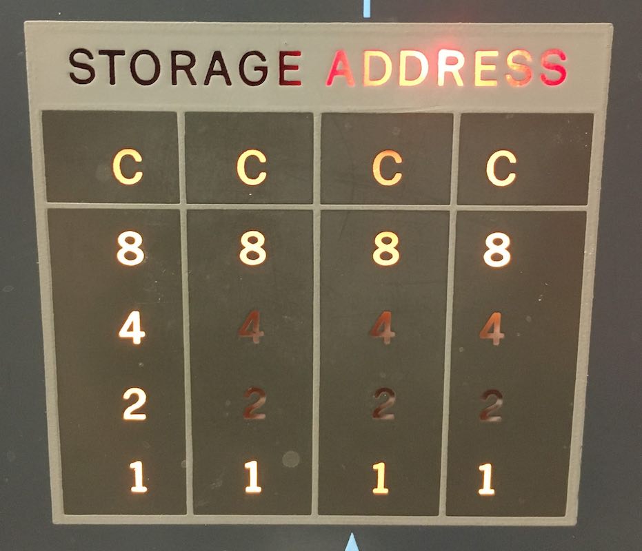
So, back to the printer. We ran the Christmas Pi deck and to our surprise it printed perfectly. Frank suspects that the ribbon failed to advance at some point, resulting in a large worn-down inkless spot. The ribbon was replaced; Frank and I thoroughly checked the oil as well and it is in tip-top shape!
Back to CT1402 card munchin' ~ we isolated the problem down to a repeatable set of behaviors that indict a relay (or relays) responsible for an erroneous hold operation. It was further identified that a few relays in the system were of the low-speed variety (719011/719010) and should have been the high-speed (719009) type.
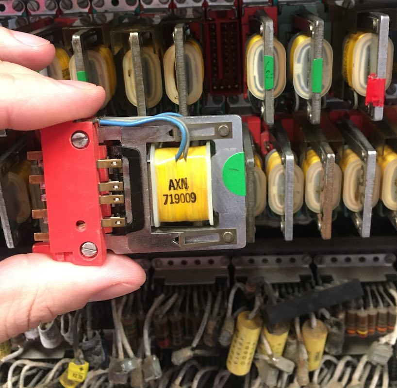
Naturally, we swapped 'em out with the high-speed type and. . . no change in behavior.
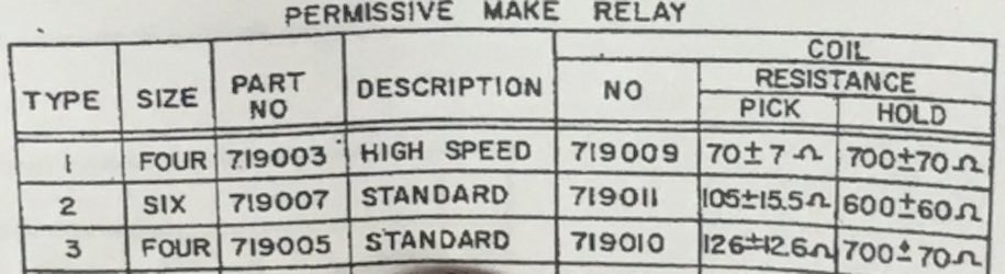
Using the LED circuit checker attached to various relays/cams, we noticed some aberrant/erratic/latent holding behavior and so it was theorized that perhaps the relay #6 socket itself was to blame since that was recently an issue on the DE tape drives which Marc fixed.
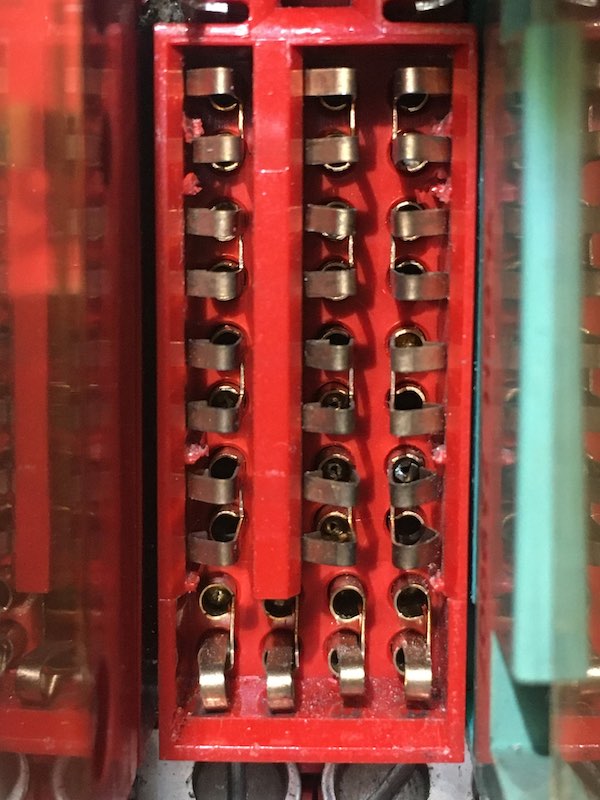
(#6 socket before adjustments to the lower-right pick/hold connectors)
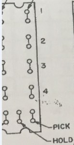
Using my favorite dental tool (actually called the spring tool), I attempted to adjust the connectors but they were pretty solid and in-place. Frank went a step further to increase the spacing between the protruding metal on the relay itself with his handy pocket knife. That's how the pro's do it:
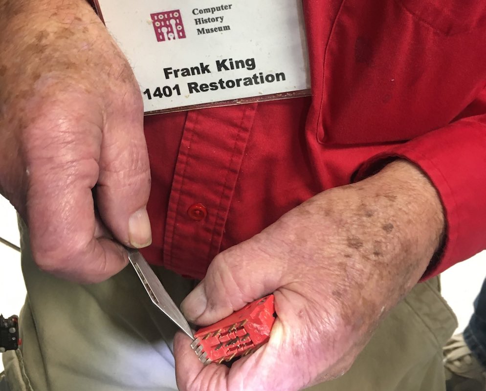
For those of you wondering just what exactly the back-side of the relay wiring looks like. Well, wonder no further...
https://www.youtube.com/shorts/YKUx4KWv9rw
I looked at each pin and the connections looked solid. So, further tracing continued; I'll wait for David to explain further on that since it was a lengthy process and he will likely recall the order of it at all much better than I can.
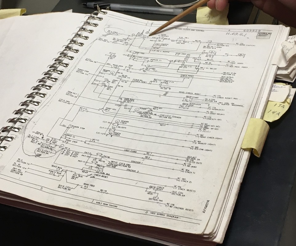
Demo
The 1/31/2024 3pm demo went just fine. I was lead and Scott Stauder was Operator for the day. Duane Sand came in to help out as well.
Keypunches were all fantastic. Microphones worked well, although maybe it's just me, but it seems that there is distortion and drop-outs with Mic #1. I tried to reduce the volume, but I can't seem to get the microphone itself to move further back so as to avoid the distortion/clipping effect.
Tape drives on DE all worked well. Sorter worked great. It just so happened that BigPrint wasn't pre-loaded and it worked well, as did Powers of Two.
Museum attendance was light, so we only had about 35 guests with 20 or so before and after. David Hoyt came in last-minute as we were shutting down with a very interested group of 8 or so people. I was able to provide them with a condensed demo which they were absolutely thrilled about.
Robert and I were cleaning up later on and there was a ton of paper I tossed out/recycled. We sure do go through a lot of paper!
That's all for now folks,
~Samuel Plainfield
|
from Marc Verdiell
|
Myself and Arda fixed CT tape #3 that was reported dumping tape in the right column. I was able to reproduce the fault occasionally. It looked as if the right reel sometimes failed to respond to the lower vacuum switch and let the tape go all the way down. Strangely this could be easily cleared by tugging on the right reel, at which point the clutch would engage quite firmly and immediately pull up the tape back up where it should be.
We burnished the right vacuum switch contacts (both upper and lower, as both are involved in tripping the tape up clutch), but that did not help.
We then checked the current going through the right up clutch while in operation, thanks to a CE panel on the front right of the tape that I didn’t even know existed. It was very low when the failure occurred.
I then checked the carbon brushes on the up clutch and found both worn, with one worn to the point of making intermittent contact. These are the “new” brushes that we had remade, so our new carbon material might be a bit too soft and wear out prematurely. They were also riding askew on the races, which might have hastened the wearout.
Anyhow we replaced the brushes with new ones, realigned them properly, and all is good. CT tape 3 is back to operational.
Marc
|
from Arda Ugur
|
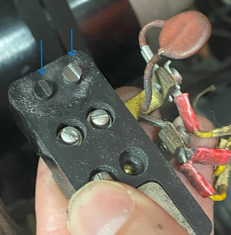
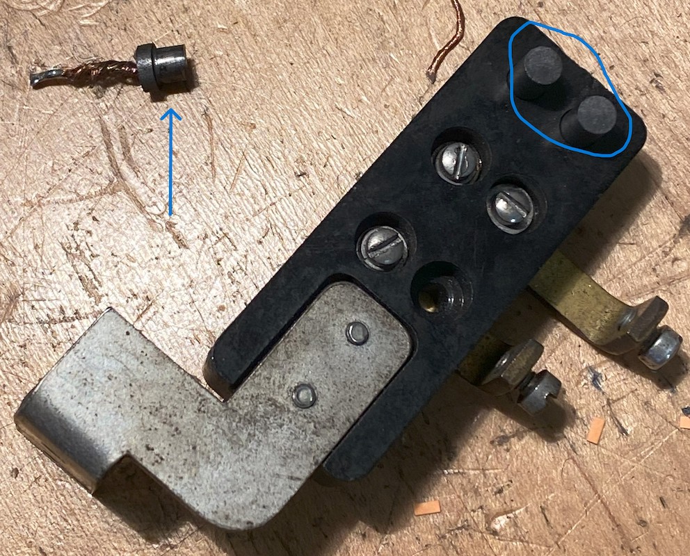
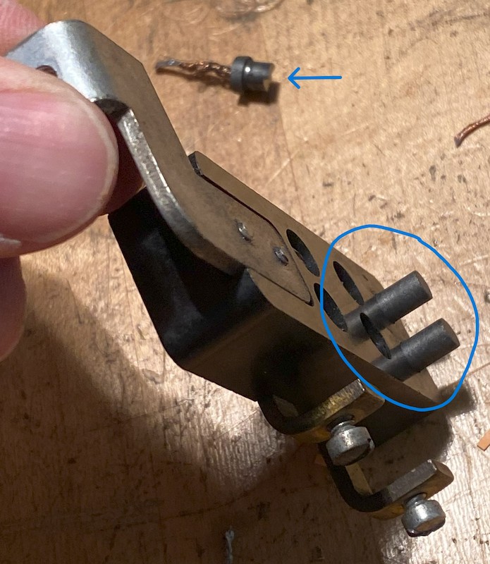
Thank you, Marc for the report. I have attached the relevant photos of our efforts.
Kind regards,
Arda
|
from Ken Shirriff
|
Summary: investigated the bad SMS card that was causing punch checks on DE. Figured out how to read card images out of the cores to help debug reader checks.
A few weeks ago I found that the CQZV card in 01B4 E23 was causing the persistent punch checks on DE. Replacing the card fixed the punch checks. However, when I tested the card at home it worked fine. Robert tested the card as well and found that it worked fine. Robert and I swapped the good and bad card a few times. With the good card, a T input of 4.4 volts yielded a good U output of -11.8 volts. However, the bad card produced an output of -5.4V which is very wrong for a U signal (should be -12 or 0). While watching, the bad output changed to -8.4 volts. I installed the bad card on an SMS extender so I could probe the signals on it. Suddenly the card started working fine! My conclusion is that a contact on the card is probably bad. There was some discoloration on the gold contacts which is suspicious.
Card image project. When a card is read, for each row, the 80 signals from each set of brushes are written directly into special cores in parallel (the RD1 and RD2 planes). After a row is read, the 1401 iterates through the 80 columns and checks if a hole is present. If so, it adds the row value to the corresponding character position to build up the character, row by row. At the same time, it updates the two hole count bits for that column, the bits that are used to catch misreads and generate a reader check.
Key point: a row from the card reader goes into the cores in parallel. The 1401 processes each row sequentially, column by column.
My idea was to use an oscilloscope to log the hole signals coming out of the cores in the 1401. This means we can look at 2 signals instead of 160 signals, which is much more practical. I wrote a program to process this data and convert it into a card image and the corresponding data. If we run this on the CT machine, we can see what card data the 1401 is processing and determine why it gets reader checks. If the data coming out of the cores is wrong, then we can see exactly what errors there are and then determine what is going wrong between the 1402 and 1401. For now, I'm running this on DE to get the process working.
Here's a photo showing the hole pattern for one row, for the two read positions. This is the hole data being read out of the cores sequentially, not the data directly from the brushes.
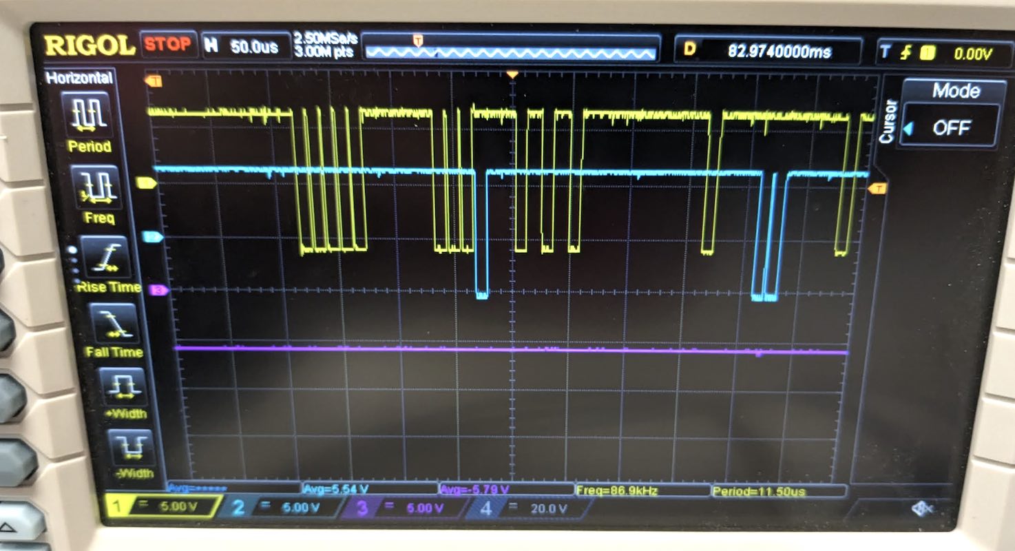
Here's some output from my program, generating a card image and determining the data on the card:
................................................................................
....................................*......*....................................
***.*..**..*..**.**..**..**..**..*...******.****.*.....................***......
.....*..........................................*.........................*.....
.........**.*.....................................*.............................
*......*......*.*..*.*...*...*..*..*............................................
.......................**..*....................................................
......*........................*..*.*......*....................................
.............*.....................................*............................
....................*...........................................................
*..*...*......*......*...*...*..................................................
............................*...................................................
,008015,022026,030037,044,049,053053N000000N00001026                   0001
Once the CT card reader stops crunching cards, I can run this on CT and see what is causing reader checks. This program will show exactly which hole is getting read incorrectly.
Ken
I noticed something puzzling about the card reader and how it drives the cores, regarding the full-write and half-write current.
There are two different circuits for how the brushes can flip the hole cores in the 1401: the full-write circuit and the half-write circuit, based on how much of the current goes through the brushes.
The 1402 Card Read-Punch CE Manual of Instruction says that the solar cell machines provide full write current through the brushes to the cores. The circuit breaker machines provide 1/2 write current through the brushes while a second path provides 1/2 write current to all the cores. Either way, the core will flip when a brush detects a hole.
The CT card reader uses the solar cell, while the DE card reader uses cams. As I checked earlier, DE machine has 180-ohm resistors, while the CT machine has the 330-ohm half-write resistors. So the CT's current through the cores from the brushes will be approximately half of DE's.
The point of this is that the manual says that cam machines use the 1/2 write circuit and the solar cell machines use the full write circuit. But our machines are the other way around. The cam machine (DE) uses the full write circuit and the solar cell machine (CT) uses the half write circuit. As far as I can tell, this is intentional and the CT 1402 had an EC to add the solar cell while keeping the half write current circuit. But this is something to keep in mind when investigating card reading issues on the CT machine; it seems to be a bit of a frankenmachine.
Relevant text:
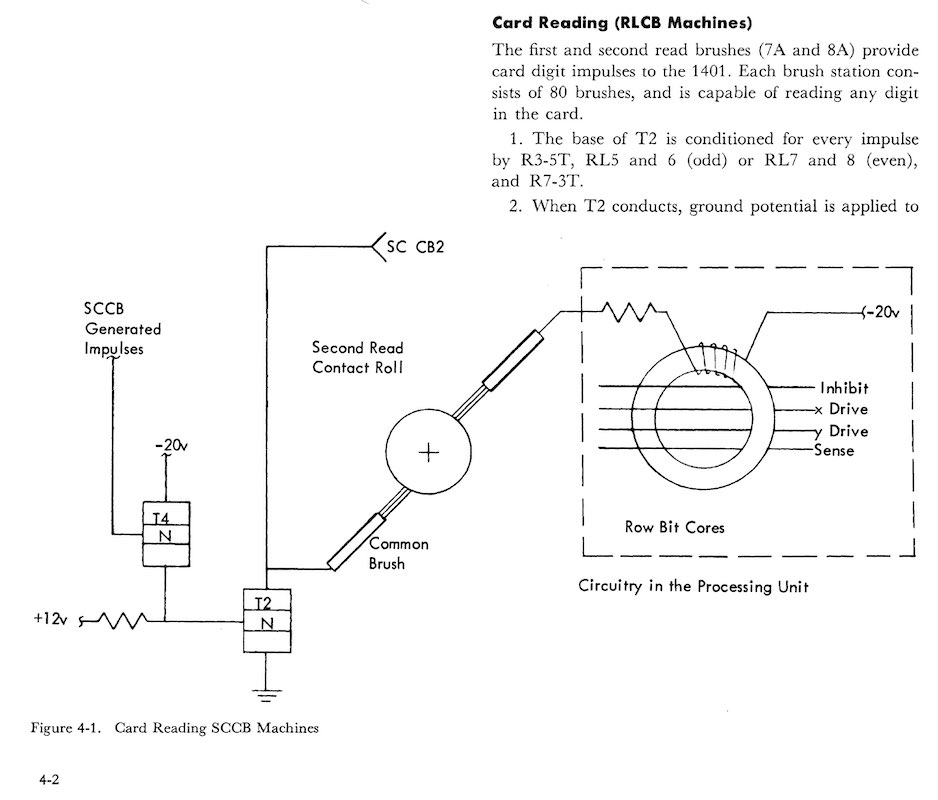
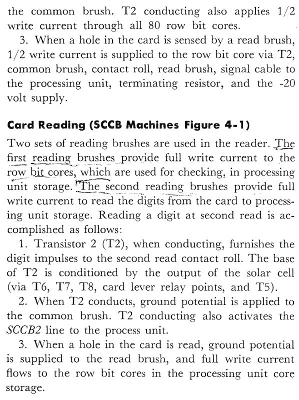
|
from David Clementson
|
First, a big shout out to Ken for his fantastic work on analyzing the data being read from the two special I/O core planes. Having this information could be the Holy Grail for those of us hunting for the root cause 1402 Reader Checks!
I don't have a lot to add to Sam's reporting on the CT 1402 Card crunching. The big picture is that we are attempting to explain the behavioral difference between the CT and DE machine vis-à-vis their NPRO behavior in the presence of a card at Card Lever #1. The DE machine continually cycles its clutch during a NPRO except when Card Lever #1 (CL1 is the lever switch at the throat of the machine, just under the hopper stack), whereupon it cycles its clutch on alternate machine cycles. In contrast, the CT machine continuously cycles its clutch when no cards are present, but if a card is present at CL1, it cycles the clutch once and only once. When the card is removed, an NPRO will again cycle the clutch once and only once. Subsequent NPROs cycle the clutch continuously. We believe the "once only" clutch cycle is responsible for the card crunching because it allows a card to be fed into the continuously running roller #2 which then jams the card into the now-stationary clutched roller #3.
One important new observation is that this behavior happens even when the machine is placed in Offline Mode via the rotary switch on the Dynamic Analyzer panel. Looking at the schematic, this switch effectively bypasses the 1401's involvement in feeding cards. This means that we can pretty much rule out any faulty 1401 logic for being the root cause of the problem.
Next we started looking at the states of several relays using the scope and an LED test light. Since the machine was exhibiting stateful behavior (it "remembered" that it had seen a card at the Lever 1 position), we reasoned that some device had to be retaining the saved state. Only its relays can do that, so we focused on them. We eventually observed that Relay #2 (Card Lever 1 relay) was being picked and held starting with the first NPRO with a card present at CL1, and released only after the second NPRO after the CL1 card was removed.
We also noticed some flaky and inconsistent behavior with that relay, which we eventually traced to a loose wire on one of the clutched cams. After tightening that connection, the behavior was the same but very consistent.
We tried to decipher the conditions that lead to the release of Relay #2, and it appears that our old friend Relay 12 is involved. This is the relay that I replaced to fix the problem some weeks ago, only to have the problem recur. But so far, the schematics seem to indicate that the behavior is by-design, although it is a little too complex for me to be sure. So we will want to scrutinize this circuit more carefully. There is also a pair of diodes (RD56 and RD57) that may be involved, so they need testing as well.
I had one other thought that maybe Mark could answer: would it be feasible to write a VHDL (or Verilog) model of the 1402's relay logic so we could determine what the as-designed behavior should be? I would think the challenge would be modeling the relay contacts because they don't have a specific signal direction (input vs. output), but rather only a connected vs. disconnected status. Does VHDL or Verilog have a means to model that kind of connectivity?
That's it for this week.
DC
>>> our new carbon material might be a bit too soft and wear out prematurely
ASTM D3363 defines a "pencil hardness test" that is used to measure the hardness of painted finishes. Pencils of different hardnesses are drawn across the test surface at a known angle and with a known force. The surface is then examined to find which pencils do and which do not scratch the surface. We could use this same technique to gauge the hardness of our brushes in comparison to the originals. If we have more brushes made, we could then stipulate he hardness we need.
DC
|
from Robert Garner
|
Dave Bennet,
Yesterday Marc and Arda found that the carbon brushes in CT 729 #3 were heavily worn, per this photo:
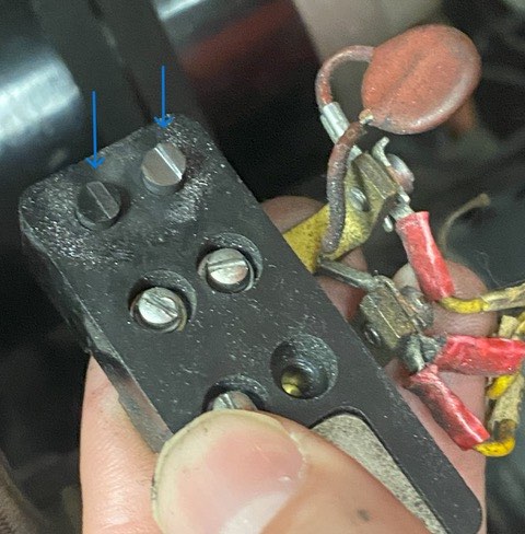
from Marc Verdiell
These are the commercial ones I believe.
Marc
Oh it’s that old?
That was one of my first heroic repair. Time flies by!
Maybe it’s normal wear then.
Asking if they have harder material, or something they recommend for riding on copper is probably worth it.
Marc
|
and a document from brush vendor to Dave Bennett
here
Marc —> Do we know if these are the “pure graphite” round ones (that you ordered back in Feb, 2016) and cut down on your lathe or are they the ones that Dave Bennet ordered from Hellwig Carbon Products?
Fyi, the email thread about replacing the carbon brushes is here:
https://ibm-1401.info/729ClutchBrushes.html
It looks like the new brushes were installed in April 2016, so they’re almost 7 years old now.
Perhaps this is representative of their normal wear rate?
Should we contact Hellwig to see if they have a harder carbon?
Cheers,
— Robert
|
from Marc Verdiell
The vendor should have standard hardness materials to choose from. You balance hardness with friction and contact resistance basically. I don’t think friction or contact resistance is very critical here. We should just ask them what materials they offer and get one or two rungs higher on hardness. Or ask the vendor for advice - they should know.
Marc
|
|
Re: "bad" CQ ZV card (and Re: Restoration Report for Jan 13, 2024
- from Robrt Garner
|
Ken,
> Robert took the bad board for testing.
I didn’t see anything terribly wrong with the “bad" B4E23 CQ ZV card, but for a trifling
weak diode (D33) and transistor (T5) in the suspected T-to-U level converter circuit.
I’m speculating that perhaps the input to the B4E23 converter (pin F, GATED PUNCH signal),
per the red arrow in the snapshot from the ALD here, also has a slow rising edge(?),
particularly given its 6 loads from a “power" driver (some loads to different gates).
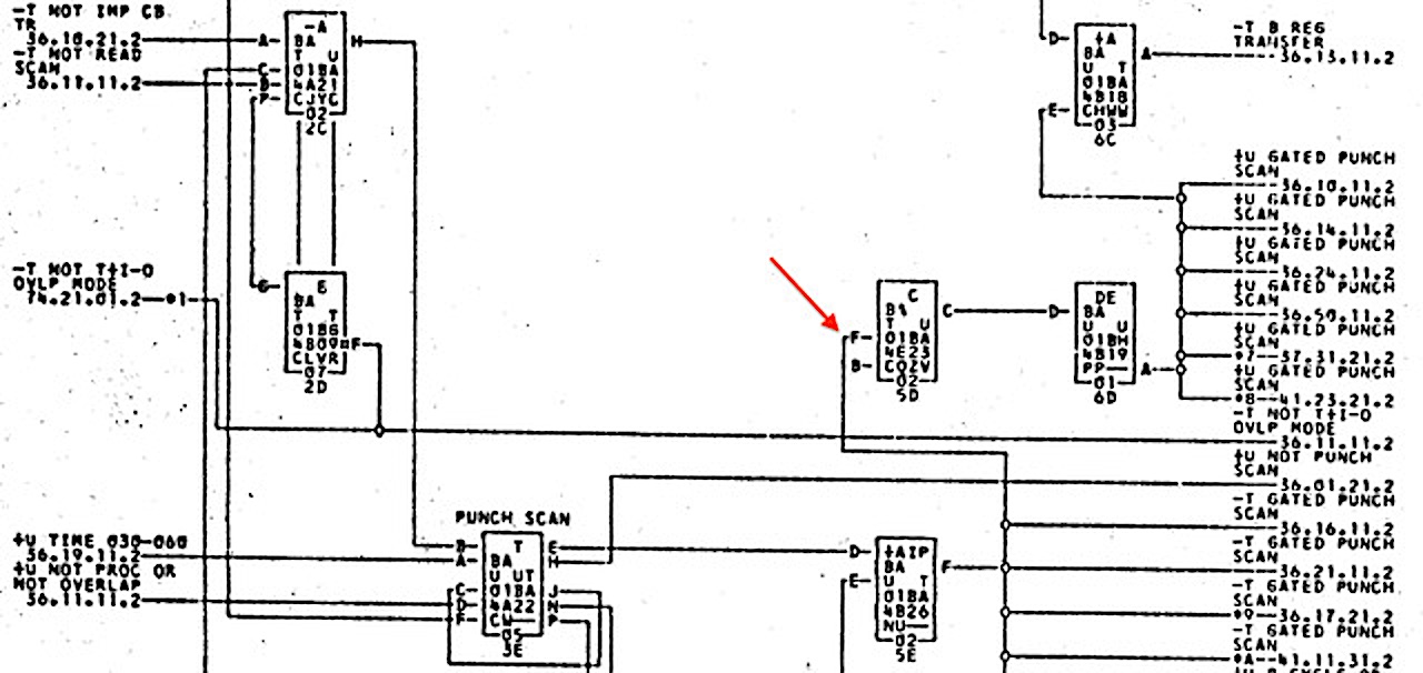
Perhaps we have a case of three coinciding issues: a weak diode and weak transistor in B4E23 plus another weak transistor in B4B26?
Did you happen to get a scope photo of the GATED PUNCH signal?
B4B26 that drives GATED PUNCH is a "PNP Power Inverter," configured as Darlington pair,
using 071 NPN transistors, each encased in a heat sink. 071’s have failed on us in the past.
(Btw, just last month I learned from John Pokoski, a member of the original 1401 design team,
that the Darlington pair was invented by Sidney Darlington at IBM in 1953.)
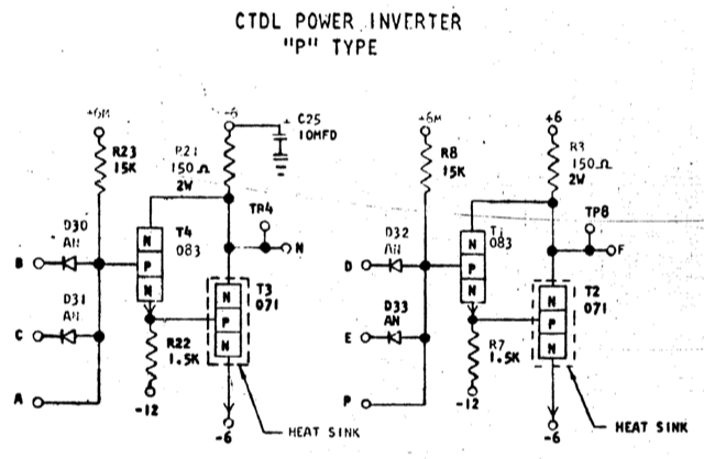
I captured I-V curves for the card’s four transistors and four diodes.
Those traces (below) show that, as you found, D33 is weak in the forward direction.
Also, the PNP 034 transistor that D33 connects to, T5, is also weak,
with a collector-to-base current gain (hFE/Beta) of 79, versus 82, 88, 86 for the other transistors.
Given that Beta is low by just 3.7% to 10%, it seems that the GATED PUNCH signal could be on the hairy edge?
Here’s the ALD for D33/T5:
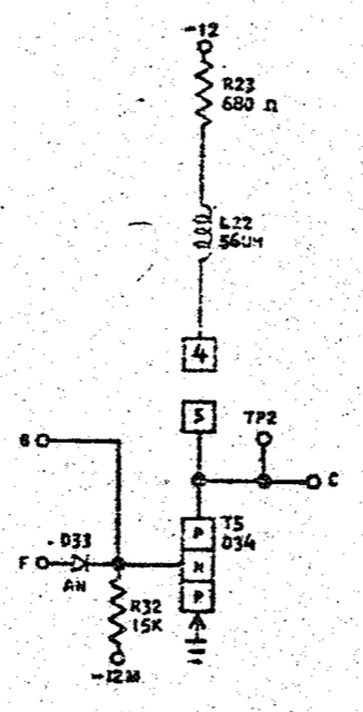
I-V curve for T5 on B4E23 CQ ZV:
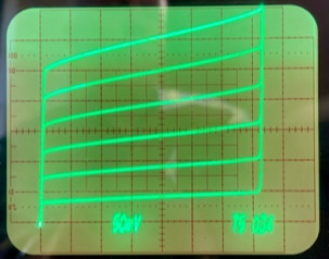
I-V curves for the other transistors the show higher collector currents at given base currents:
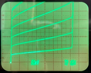
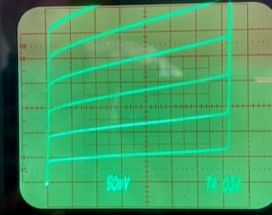
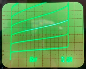
(Note: I-V transistor traces show collector-emitter voltage on horizontal axis vs. collector-emitter current on vertical axis as a function of increasing base currents.)
I-V curve for D33 that connects to T5 on B4E23 CQ ZV:
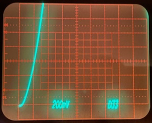
And the others with quicker rise times, implying a higher current at a given forward voltage:
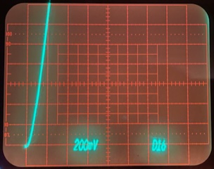
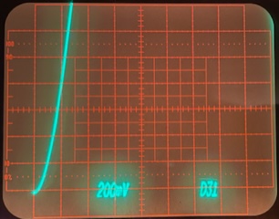
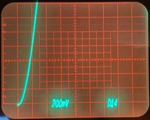
(Note: I-V curves for diodes show cathode-to-anode forward voltage on horizontal axis vs. current on vertical axis.)
I’ll next measure the converter's in-to-out propagation delay (w/a decent load)….
As Ed says, wish us luck,
— Robert
Ken,
Oh, forgot, here are photos of my hFE/Beta readings for the transistors, T5 first:
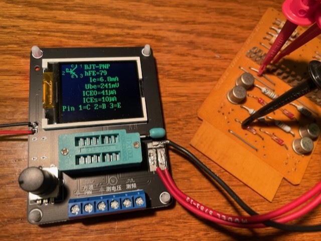
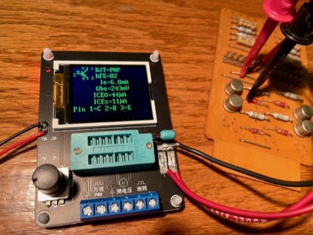
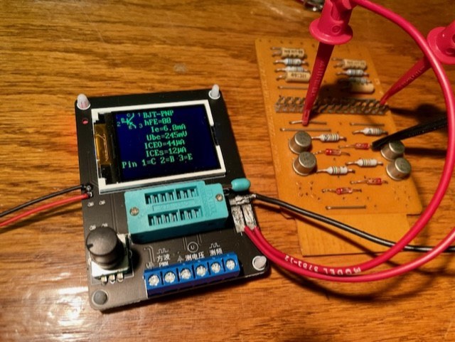
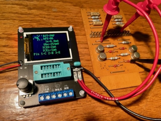
Cheers,
— Robert
|
from Ken Shirriff
Robert,
Thanks for checking out the board. It's a bit puzzling that board works okay out of circuit, both for you and for me If you bring in the board on Wednesday, I can do some more experiments. The input to the board looked okay, so I don't think the issue is with the previous board. Moreover, the bad voltage level is static, so it's not an issue with rise time
Ken
|
from David Clementson
It could be that the interconnections going to or coming from the board have become ohmic. That would explain the difference between the behavior on the bench vs. in the unit. An ohmic fuse connection caused by dissimilar metal contacts brought down my MBZ last week. It took days to find and just a few seconds to fix.
DC
|
from Robert Garner
|
David,
> Does the ringing change if you relocate or even just put your finger near your scope probe’s ground connection?
Nope.
I had the same leeriness wrt to scope grounding. However, due of the unterminated nature of the traces
(and the fast input edge rate), the ringing appears to be real (for all four T-to-U converters on the board).
Each transistor output trace goes to three non-terminated "opens" on the board:
- the edge connector,
- a programmable tab post in middle of the card, and
- to a test point at the non-connector edge.
Putting a 10k-ohm load on the output greatly diminishes the ringing, as does measuring with a 50-ohm probe (photos below).
I suspect that the ringing doesn’t show up in the 1401 system itself, but that would be worth double checking.
I also suspect that the slower input transition times in the actual 1401 doesn't result in excessive ringing
(as the output transitions would be slower, per the slow low-to-high output rise times that absorb the reflections).
On left, here’s what the ringing looks like on my Tek TDS 3054 (500-MHz, 5 GS/s) scope.
Nearly the same as on my Tek 7834 on right:
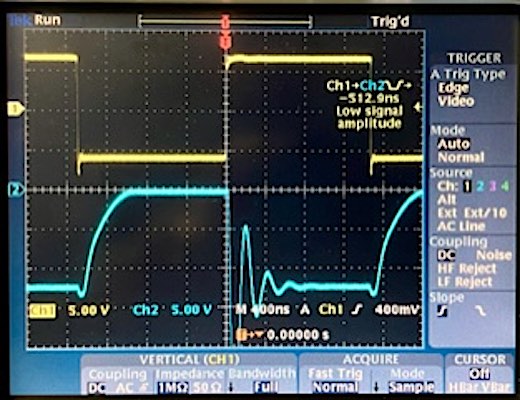
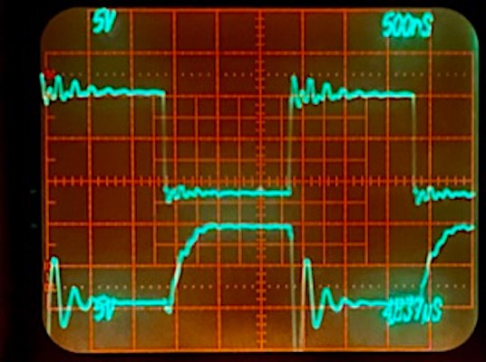
Here the ringing is much diminished with a 10-kohm resistor in series with the output (placed at the programmable tab):
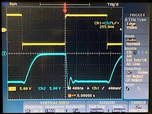 <
<
And almost completely attenuated with a 50-ohm probe (back on my old Tek 7834):
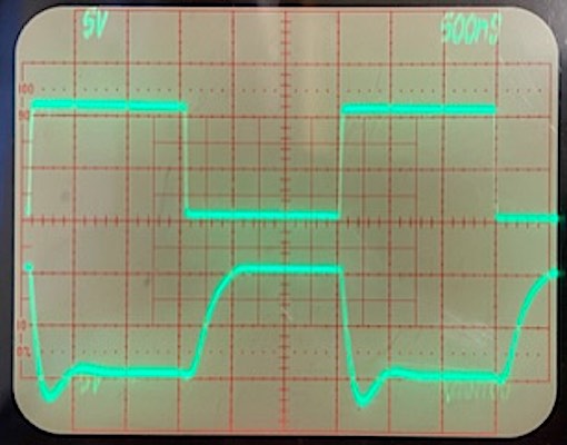
Of course, as Ken pointed out, none of this explains a static output level of -6V
(unless the T input is so abnormally close to ground that the transistor is only partially on, resulting in a curtailed U level.)
Cheers,
— Robert
p.s. Over time, I think I read every page of the outstanding “Handbook of Black Magic” book! :)/
|
|
Apple Day -- Sun 1/28/2024
- appparently some two thousand Apple employees are expected to visit CHM
from Pat Buder
On a Sunday with a museum buyout by Apple Computer (over 1,000 people),
Duane Sand and I gave a special demo to an estimated 90+ visitors. It
was not feasible to ascertain their origins. In addition, we had an
estimated 300+ guests drop by for mini demos and/or BigPrints between
10:00 am and 5:00 pm. The moments when no guests were in the room were
relatively rare.
When I got to CHM I verified that DE was functional. Shortly after Jack
Ghiselli arrived he began seeing if he could coax the CT 1402 to read
cards. Instead it was munching them. He cleared one jam but the problems
persisted, so we ran on DE. We did use the CT tapes #1, #2, and #4 for
the tape demo in addition to all three DE tapes so that more people
could see the action. Toward the end of the day the DE 1402 got
ocassional reader checks, all of which went away on reruns.
Karen Sun joined us and, at my request, duplicated more "decoder" cards
(with all printable characters) for us to use in explaining card code.
Thanks, Karen.
Larry Hara also stopped in between leading Revolution tours. Jack and
Larry used VOBJ to fix problems in several BigPrint decks. See Jack's
separate report for details.
There were peak times when all five of us were busy. Thanks to all of
the helpers.
All three kepunches and the sorter ran fine. The DE 1403 ran fine most
of the day. For about the last 45 minutes, the printing got progressivly
more faint. During the 20 minutes before closing I just had guests punch
their name cards but didn't print them because the results would have
been unreadable. I tried seating the chain housing and latch more
firmly, but it didn't help.
I used mic #1, which had some dropouts. It may have been battery
problems. Even though I swapped in fresh batteries from the charger
before the demo, I'm never sure that they are truly fully charged.
All things considered it was a fun if sometimes hectic day. As usual,
big thanks to the restoration team for keeping us supplied with enough
working machinery to conduct the demos for a grateful public.
Pat
The following arrived Feb 1st, apparently there were transmission problems - Ed Thelen
As demo lead that day I was the one who wrote the numbers in the blue
book. They were 90 for the demo, and 350 others. My counts reflect every
person who entered the room, regardless of when theyt arrived or if the
left early.
Demo count
Jack gave me a count he took at the start of the demo. I've lost what
that number was. In any case, probably 20+ more came in during the demo.
The room was almost full. In fact, Larry Hara took it on himself to
stand by the main entrance and re-direct those who couldn't get in to
the the exit door. Thanks, Larry! Inasmuch as we were running mainly on
DE, that actually wasn't a bad place to be. During the recent holidays
and other busy times we frequently have 90, 95, or even 100 or more
there. You can go back in the blue book and see what was reported. We
were almost full, so that's how I derived that number.
Drop In Count
The room was open from 10:00 - 5:00. I know, because I was there all
that time. So excluding the demo time, that leaves about 6 hours. 350
visitors / 6 hours = ~60 visitors/hour = ~1/minute (average). Many times
throughout the day we could see 10-15 people at the keypunches, another
10-15 waiting for BigPrints plus a few others. That's 30+ people in the
room just at that instant. Those are peak times but in off-peaks we saw
an almost constant lesser flow. The first 45 minutes of the day were
slow. That's a good thing because it gave us a chance to fix the decks.
Jack and Larry interleaved running VOBJ with BigPrints and they got much
done. Thanks, guys. In the last hour there was the usual rush of people.
I only got out of the room by about 5:10 because I couldn't run any more
BigPrints due to the DE 1403 faint printing problem.
Note that the number of BigPrints does not = the number of visitors. I
think it's less than half. A common visitor group has 2 parents and 1 or
2 kids. Usually only the kids punch name cards. Also the card veterans
usually aren't anxious to punch yet another one.
Several times during the day I convened the 1401 demonstrators and asked
for crowd size estimates. No definite figures were offered. In fairness,
when one is as busy as we were, you really don't think of counting.
If these numbers still seem high, by all means reduce them. Large crowds
of moving people are very hard to accurately asses.
Pat
|
- from Jack Ghiselli
|
I came in as an extra to help with the 1401 Demos for Apple Day Sunday 1/28/2024, Demos were on-going all day.
The CT1402 reader had a 3-card jam at the end of yesterday's 1:00 demo. Sam Plainfield stayed late and cleared it. Unfortunately this morning CT1402 again got a new 3-card jam. I cleared out the new jammed cards, but the CT1402 still won't feed cards. So demos used DE.
The deck that got crunched was a Lincoln. So, there is a Lincoln deck missing its first 3 cards (#0001 - #0003). On card #0004, we wrote a note that the deck had missing cards, but due to ongoing demos we didn't have time to fix the deck.;
The CT1402 Reader NON-PROC-RUNOUT rocker switch works, but seems to be physically loose. Can somebody fix this before it breaks? I don't know how.
Pat Buder (Demo Lead) reported that when he came in NONE of the BigPrint demo decks worked. Using DE, Larry Hara and I ran VOBJ on some of them and found these errors:
- BigPrint deck #1: One card caused a validity check. We duplicated the card and the error disappeared.
- BigPrint deck #2: Card #0004 had been moved to the end of the deck, just before the final card #0111. We fixed this.
- BigPrint deck #3: Several of the cards were upside-down in the deck, and the last card was missing. We fixed these problems and the deck now works.
- Since demos were starting, we did not have time to look at BigPrint deck #4 nor the BigPrint deck labelled "Frank King".
Some of the demos used the CT TAU and 729 Tape Drives. Drive #3 ran for a while, then dumped tape into the right-hand (output) vacuum column and went Not READY. We were able to unload and rewind the tape, and dialed the drive to NOT OPERATIONAL.
Jack Ghiselli
jghiselli@sbcglobal.net mobile 1-408-839-1051
|
from Ronald Mak/SJSU
|
From the demo reports, it appears that often the weak link is the card readers. The printers work great!
Is there a way to load the demos onto mag tape (or the PC tape emulator) and run demos from there as a backup whenever the card readers are being cantankerous?
Just a thought ...
— Ron |
from Jack Ghiselli
Hi Ron,
We are working on it. I have an ongoing project to build a multi-demo tape. The idea is we would boot the tape and use sense switches to select the desired demo. Might even have "Lincoln" on there! My project is moving very slowly. It turns out we have problems with the tape drives almost as often as the card reader. But, we'll keep trying.
Jack Ghiselli
jghiselli@sbcglobal.net mobile 1-408-839-1051
|
|
IBM 1401 Lab Demo 1/27/24
- from Karen Sun - 1100 AM
|
Karen Sun soloed today's 11 AM demo as Paul couldn't make it due to
his medical issues. 25 visitors showed up with another 10 visitors
before and after the demo. Those foreign visitors were from Australia,
Spain, China, Korea, Japan, India and Norway. Quite a few used 1401
machines and brought their grandchildren or children to the lab.
I used keypunch #1 and #2. The sorter worked smoothly. I turned on
both CT and DE while I successfully ran the Big Print on CT. I tested
the DE with Powers of Two and Lincoln yet it didn't load any card nor
any check lights on. I turned DE off afterwards with its power on.
729 Tape Drives on the CT has #1, #2 worked. #3 had one end of the
thread fall off and I flipped it Inoperable. #4 didn't start any
movement no matter what buttons I pressed.
The audience was very warm and shared a lot of comments and their
personal stories with me. A Japanese Revolution guide brought his tour
group to the demo and after the demo he helped me punch name cards as
well as tear off the Big Print. Thank you :--))
|
from Stephen Madsen - 1 PM
from Samuel Plainfield - Maintenance bit
|
I arrived a bit later in the day and cleared the CT1402 jam; I tried loading a Lincoln deck but it catastrophically crunched 3x cards immediately. I cleared that mess as well and re-built the deck.
We'll be back at it again Wednesday,
~Samuel Plainfield
|
from Pat Buder
|
Thanks, Samuel. We have a huge day tomorrow (Sunday) with 2100 Apple
visitors scheduled, so we need at least one working system.
Pat
|
|
1401 demo on 1/24
- from Scott Stauter
Tim Robinson and I gave the 1401 demo to 17 guests at 15:00 and 4 more afterward. The foreign visitors were from South Korea.
The audio equipment and all the keypunches worked OK.
The sorter worked fine.
We used the DE1401 system for the demo, but the CT system components also worked.
All three tape drives on DE1401 worked.
Scott Stauter
|
|
CHM IBM 1401 System Maintenance - January 24, 2024
- from Jesse Nichols
re - Hole in floor, bad place link to hole
|
Hello 1401 Team,
We investigated the issue. The hole has been repaired by simple switch of the board. Moving the square board with the hole from the walking path - to under the 2nd 026 Key punch machine out of the general walkway to the AV closet. We can thank David Clementson for coming in early to fix this issue. I’ve attached some pictures to show what was done. Thank you everyone with your help with this. Teamwork!
Let us know if you have any questions or concerns.
Thanks,
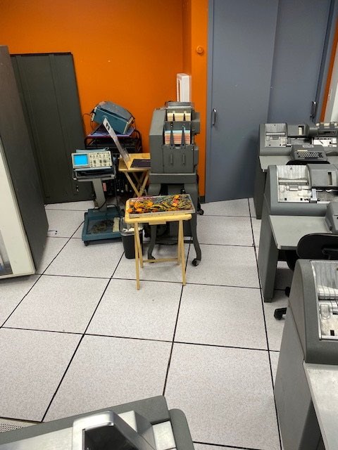
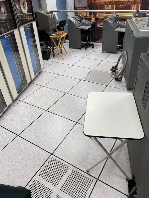
....................................
Jesse Nichols III
Museum Services Supervisor and Volunteer Coordinator
Computer History Museum
|
from Ken Shirriff
|
A few things:
DE punch check: I measured the suspicious card in circuit. 01B4E23 pin C showed -6 volts. This is a U output so it should be -12 or 0. Thus, the card was producing a bad voltage right in the middle that would sometimes signal that a punch was happening. I swapped the card and the new card shows -12 volts as expected. The transistors all seemed ok with the multimeter but the diodes showed forward voltage drops of .292V, .309V, .330V, .358V, which is a wide range. The highest was in the bad circuit so my suspicion is the diode. Robert took the bad board for testing.
CT 729 tape #3. This was reported to not unload, and it was not unloaded. I was able to load and unload it several times, so this seems to be a transient problem.
DE console lights. Samuel and I were comparing CT and DE to see if it was normal to have a word mark on a character read from a card. (Yes, if you're using the 80/80 list, it doesn't clear the word marks out of the read buffer.) We noticed the C bit was not lighting up. To make a long story short, we replaced 4 bulbs, one of which immediately failed, but now the bits all light up. I don't know if this is a higher failure rate than expected.
029 keypunch in the back room, connected to the PC. I took a look at this and found a few problems. It is stuck in numeric mode unless you hold down alpha. The ribbon is stuck and dried up, so it doesn't print. I couldn't find which program on the PC will operate the punch. Stan, do you know the status of this machine?
CT reader checks: I talked with David, Samuel, and Robert about the reader checks on CT. David thinks that the timing looks okay so there might be a problem in the 1401. I'm thinking about what we could instrument in the 1401 to find read problems. To see the signals from the brushes, we'd need to solder wires onto the paddles under the core memory. (The DE has a few of these wires added by someone in the past.) Logging this data would give the clearest indication of what is going on. I could also look at the data as it comes out of the core memory for processing during the read, which would be easier to obtain but harder to interpret. If this raw data is right, then we'd know the problem is in the 1401. So I'll see if I can come up with a plan for next time.
Ken
|
from David Clementson
Tape Emulator PC:
I recapped the PC motherboard, installed a fresh CMOS battery, and reinstalled it in its case. I installed the original disk drive that Shmuel imaged. The machine booted fine and loaded Windows. The VGA connector or cable is a bit dodgy at the motherboard end. One color will drop out unless the cable is arranged just so. I'll bring in a replacement cable to try that, or else we may need to resolder the motherboard connector.
CT 1402:
We looked at the Reader and Check brush timings and found that they were spot-on. The "all-fives" deck ran flawlessly after the machine had been run a bit, so we looked at the Check brushes (yet) again. We found that the interposer connector plate was a bit loose on the low-numbered column end, so we removed it for service. We found two brushes that had errant bristles, so we replaced them. We also found a good sized divot in the carbon roller. After replacing everything we still had Reader Checks. So next week I recommend we revisit measuring the resistances from each brush to the common brush, this time with the rollers spinning. We can do that with a constant current source and a digital scope, and can access the connections via the RC connector at the rear of the machine.
That's it for this week.
DC
|
from Samuel Plainfield
|
I have a surplus of PCI/AGP video cards (VGA and DVI, etc) that should be compatible with that Tape Emulator system, if we'd like to skip the re-soldering of the onboard video card. I'll bring 'em in just in case.
The loose interposer board on CT1402 read check was producing consistent errors on brushes 1-10. Adding briefly to what David already said: after we fixed it up, the read checks did indeed persist, however with some improvement and differences. The read checks were consistent on brush 30, 31, 50 and 51. However, a bit later on I ran a quick BigPrint for a couple Apple execs prior to shutting everything down and it ran through perfectly with no read checks ...
Also, to note, we ran a deck of all blank cards to ensure that the read checks were real and not originating from the 1401 somehow. That test resulted in no read-checks, proving that indeed the problem is 1402-related, as Ken suspects.
The divot in the read-check carbon roller is quite egregious and hits on row 13-14, however, scope tests show that it doesn't seem to affect conductivity in any measurable way.
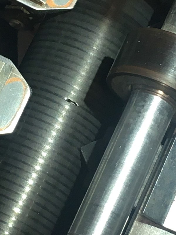
We also attempted to chase the loose wire on the (CT1402) cams but it *seemingly* led to the STOP button... but further testing couldn't directly connect the wires via the multimeter. So, that remains a mystery for now.
~Samuel Plainfield
P.S. - With the Apple folks visiting, don't forget to remind them that removing important connectivity like USB-A ports and headphone jacks isn't innovative, "courageous" or an upgrade, it's a downgrade.
|
- from John Howard
|
RELAY STATUS
This cabinet contains our inventory of good spare relays, it is located in the lab.
Permissive Make Relays
8 6-Pole and 8 4-Pole relays in the cabinet
I have an additional 3 6-Pole relays in repair.
Wire Relays
4 6-Pole and 4 4-Pole
Each repaired relay has a green identifying label on the top.
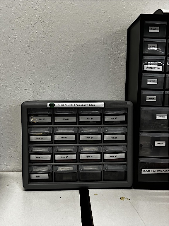
John
|
|
CHM 1401 Demo Sat 01/20/2024
|
- from Jack Ghiselli, - 11:00 AM Demo
- from Lary Hara - 1:00 P.M.
- from Paul Laughton
|
Please report AV issues in separate email to jplutte at computerhistory dot org
|
|
Wednesday 1/17/24 demonstration
- from Tim Robinson
|
Scott Stauter and I gave the 3pm Wednesday demo.
We had 44 visitors including some from Mexico and Canada. Most others
were locals.
Just before the demo the restoration team had still been working on the
CT reader and they left the machine off, so we used DE for the demo and
it performed flawlessly. We ran both bigprint and powers of two for the
demo then reloaded bigprint for after demo prints with no problems. All
three tape drives worked fine. After the demo the restoration team
returned and told us the CT reader was in fact working, but they were
still doing more margin checks to make it even better.
The cardpunch closest to the wall was marked "does not feed". We used
the other two and both work fine with good clear printing. The card
sorter worked well, as did the microphones.
Tim Robinson
|
Restoration Report for Jan 17, 2024
- from Ken Shirriff
I worked on the German machine with Marc and we fixed some things.
-
I traced the punch check issue to a bad card on Saturday and replaced the card. The card tested fine so I put it back in the machine and the punch checks are still gone. (I can't reproduce them by putting a bad value in the B register.) Perhaps the contact with the card was bad? The card is 01B4-E23 CQZV 36.22.11.2.
-
The card reader also had Reader Stop problems. It would hang up on the first card or read a few cards and then stop. Marc went through the card deck and found some marginal cards. Removing them helped a lot. He also adjusted the throat and that also helped feeding. It now feeds more reliably.
-
DE 729 #1 has been unable to load for a while. The problem was that relay 107 should drop, but it stayed latched. (Unlatching it by poking it manually permitted loads to work.) I swapped the relevant relays with no effect. Marc noticed one of the contacts in the socket for relay 111 was bent. He fixed the contact and now the drive is back in service.
-
The Go Down Time knob in the TAU panel had come completely loose. Marc fixed this while I watched :-)
Ken
|
- from Robert Garnner
|
Ken,
> I traced the punch check issue to a bad card on Saturday and replaced the card. The card tested fine so I put it back in the machine and the punch checks are still gone.
I may have some troubling news: Sam hasn’t reported this yet, but late yesterday afternoon we fired up the DE 1401 (to demo it to some delightful Danish visitors*), BigPrint would not load. The 1401 panel turned red, including the PUNCH check light (and the B register). After 4-5 attempts, it finally successfully loaded (and PowersOfTwo, but not again after they left.)
I’m wondering if you might want to reinsert in the replacement CQZV card and take a second look at the (likely) faulty one? Perhaps one of its transistors is marginal or has a loopy I-V curve (hard to spot w/o an I-V trace)?
— Robert
* The Danish visitors came into the 1401 Lab after a Samsung event. They had never seen/heard of a 1960s computer and were gobsmacked with our setup. When I asked if they might guess the 1401’s memory capacity, it was beguiling to hear their first guess: 5 megabytes!! :)
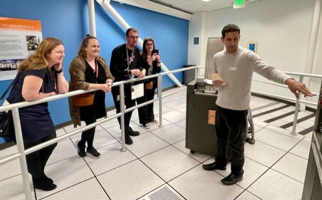
|
- from Marc Verdiell
And another one of my mega achievements today was to change one of the neon bulbs on the service panel of the DE tape #1 that Ken was debugging. We were led astray by the bulb not working. They are a pain to change and require special 80V neons, but we now have a whole stash (I marked the bag clearly), so we should change them when needed. Or do a thorough job à la David and change them all - most of them are already pretty dim.
Marc
|
- from David Clementson
|
CT 1402 Card Munching:
I proposed to the team that we do a full-court press effort on the 1402's cams, much like we did for the relays. It's not so much that we suspect a bad cam, but if there was a bad cam we wouldn't know about it until we looked. So we set about isolating each cam in turn, carefully measuring its ON resistance, and noting its make and break angles for each lobe. We did each measurement twice to get a little bit of an idea of the cam's repeatability, and of course rechecked any value that fell too far away from the expected value.
We started using the milliohm meter, but found that its response time was rather slow which made finding the make/break events difficult. So we settled for using the ohmmeter on the blue DVM. It proved to be sufficient for finding gross contact problems.
The data are summarized in the attached spreadsheet.
SpreadSheet as .pdf
Two limit value cells at the bottom of the sheet drive the conditional formatting that highlights out-of-limit cells. The executive summary is that we found two cams with high resistance contacts, and the timing of most of the cams was reasonable. We were able to clean the high resistance contacts and bring them down to values similar to the others, so this alone was worth the effort.
Mark discovered a free-hanging wire in the cam area that looks like it ought to connect to one of the cams. We checked the actual number of connections to each cam terminal and compared them to the schematic. All wires seem to be present and accounted for, but next week we will try to trace this wire to see where it goes. Mark agreed to bring in his wire tracer, and I will bring in mine. Marc suggested that these tracers might not work well with the machine's wiring harness, but we'll give it a try. We could also remove each relay and check its socket for continuity to the hanging wire, since it is likely that if the wire really is supposed to be connected, it would go to a relay.
1042 Reader Checks:
After collecting the cam data, we ran an "all fives" deck to check the Reader brush health. Once again, brush #3 was showing problems as did one of the middle brushes. So we swapped the wires that connect to Reader brushes #2 and #3 and reran the test. The problem stayed with brush #3, meaning that the brush itself must be the problem. Since we've replaced brush #3 several times already, we had a look at the carbon roller. I tried resurfacing the roller with some 600 grit abrasive paper, under power this time. It was a little tricky avoiding having my fingers ingested by the running machine, but I was able to escape unscathed. After cleaning the roller with alcohol, we repeated the test and found that there were no errors. Hooray! So we did the same procedure on the Check roller, but unfortunately we still got Reader Check errors.
So we removed the whole Check brush assembly and took it to the workshop. We replaced/readjusted about six brushes and reinstalled the assembly into the machine. Subsequent testing gave some anomalous results, but we didn't have time to debug them.
So next week we'll look into those anomalies. And I think it would be a good idea to have a look at the brush timing using the scope. It would probably be a good opportunity to install the new solar cell code wheel for the brush timing check.
Tape Emulator PC:
Finally, the replacement caps for the Tape Emulator PC motherboard finally arrived, so I will replace them this weekend.
DC
That's it for this week.
|
- from Samuel Plainfield
|
Following up briefly on the software side of both machines, a few things to note:
CT1402:
After the check contact roller was complete, I/O check was turned back on and the 5's deck was tested again. The reader checks persisted but this time in a strange manner:
~ Switching to Storage Scan, the first brush that registered was 107 and CHECK RESET lit up. 107!
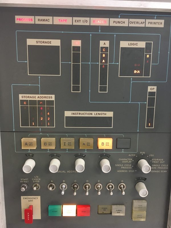
~ Pressing START, the second was 077.
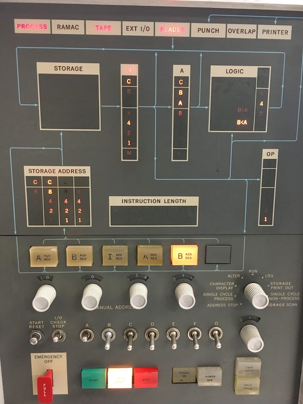
However, pressing START again after that to see what more brushes were problematic would not work and the display would not change after 077.
The CHECK RESET light stayed illuminated, preventing further data from showing. Pressing CHECK RESET would restart the 107, 077 loop.
This behavior is not standard per the manual as far as I know -- I'd like Frank to take a look, assuming this behavior repeats next week.
DE1402:
Towards the end of the day, Robert and I were doing some tests and the 1402 resumed having some punch check issues with an OVERLAP error in tandem. Eventually, all of that stopped altogether and the 1402 wasn't appearing to send any data at all over to the 1401. That is, pressing LOAD wouldn't pull cards and the OP code register would remain completely empty on the display. (Also, the rollers would stop running immediately when the LOAD key was released.)
What might cause the 1402 to not send these hardcoded signals over to the 1401?
That's all for now.
~Samuel Plainfield
|
|
IBM 1401 Demonstration Sat. 1/13/24
- from Larry Hara - 11:00 AM
|
Thanks to Jack for editing the format of this table, can we use the following as a standard for future 1401 demo reports? I've highlighted items where we would appreciate the Restoration Team's help and expertise and for the next Demo Lead and Operator to be aware of.
Summary
- CT was funky but worked - thanks to the Restoration Team!
- Great audience engagement with questions that were great lead-ins to what was coming up (e.g., how is the 1401 connected). About 12 visitors hung around to continue to ask more questions after the demo.

|
- from Stephen Madsen - 1:00 pm
|
Duane Sand and I demonstrated to 82 visitors + 20 after the demonstration. We had hardware problems just before the demonstration, so we had little time to talk with visitors.
Microphones: OK
Keypunches: The one nearest the closet would not feed cards.
Sorter: OK
DE: The morning crew said DE was not working, so we did not try it.
CT: Tape #1 had a problem. Tape was wrapped around the back of the hub on the input reel. The reel was removed and left on top of the unit. The bad part of the tape was discarded. Pressing the reset button would not stop the tape movement.
The unit would not unload. We set it to inoperable. Tapes #3 and #4 were inoperable, so only #2 was working.
The reader stopped reading cards sometimes, but we were able to make it work again. The printer worked OK.
Stephen H. Madsen
|
|
Restoration Report for Jan 13, 2024 - Saturday
- from Ken Shirriff
|
I worked on DE before the Saturday demo, and fixed the punch check problem, but other problems remain. Summary: a bad SMS card made the 1401 think it was punching. If the machine randomly powered-on with bad parity in the B register, this triggered the infamous punch check error.
Details:
The symptom was that DE sometimes came up in a state with a punch check and was unusable. Pressing Check Reset on the punch would clear the check while the button was pressed, but then it immediately came back. This problem was random. Sometimes it would happen for hours, and sometimes it would go away for months.
The punch check circuit is complicated. Normally a punch check happens if the read brushe hole count disagrees with what was punched. However, there is a second way to get a punch check: the mysteriously-named "ALLOW B REG CHECK". What that means is a parity error in the B register. The motivation is that if there was a parity error in the B register while doing a PUNCH SCAN, that indicates a corrupted value, so it triggers a punch check.
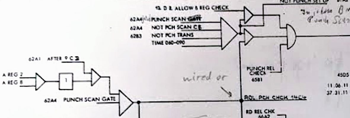
This check should only happen when you're doing a punch scan, of course. But the PUNCH SCAN signal was erroneously asserted, which explains the mystery of why punch errors happened when the punch wasn't being used. I found that card E23C (36.22.11.2) had a voltage of -6.2V. I assumed this was okay, but then I took a closer look. This signal is +U so it should be -12 V or 0 V; it was outputting a bad voltage right in the middle, which was being interpreted as high. I replaced this card and the punch checks went away.
How to reproduce and clear the punch check error.
The punch check happens if the B register powers up with a parity error, which is why this problem was intermittent, but also didn't go away once it happened. However, if you load a good value into the B register, the punch check can be cleared:
Steps: switch to Alter, put toggle switches to a valid value (e.g. one switch to the left), press the B AUX REG button, toggle the ENTER switch up, switch back to Run.
And if you load a bad value into the B register, the punch check returns.
The one loose end is that I couldn't find any problem with the bad CQZV card when testing it at home. I'll do more testing next week to see if I can get a smoking gun here.
Unfortunately, DE still has other problems. It sometimes doesn't feed a card (picker knife problem?) and it sometimes gets bad data in the B register which triggers the jackpot of error lights: PROCESS, READER, OVERLAP, STORAGE, and B. I thought there was a problem with the parity calculation, but I discovered that my oscilloscope's input #1 was somehow in Invert mode, so all my measurements from Wednesday are suspect. (This explains the mysterious +10 V signal from an SMS card that doesn't have any power above +6V.) So I'm unsure if parity is getting calculated wrong or if the B register has genuinely bad data.
Main lesson: don't assume that -6 volts is a correct low signal. Check if the signal is a T or a U and verify the voltage. For reference, here are the voltage levels:
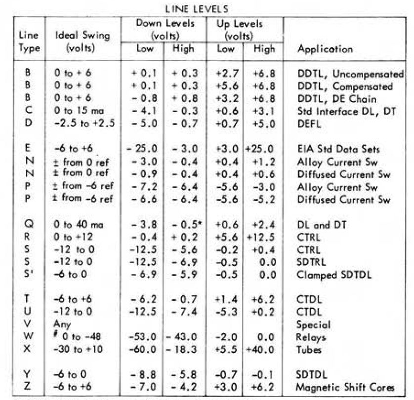
Ken
Ken,
Thanks for coming in today to find and shoot the nasty and tenacious DE punch check bug!!
(I trust you might be able to sleep some now. :))
— Robert
|
|
Restoration Report for Jan 10, 2024
- from Ken Shirriff
Marc and I looked at the various intermittent problems on the DE 1401 and made some progress. The problems all seem to have the B register parity check as the root cause.
Problem 1: Reading hits multiple errors: Process, Reader, Overlap, Storage
Problem 2: Punch Check error that can't be reset.
Problem 3: B register bits have a parity error but the B register error light sometimes doesn't illuminate.
These errors (at least 1 and 2) have happened intermittently for a long time. They showed up long enough for us to do a bunch of debugging.
Conclusions:
- The B register was valid CB421 but showed a parity error. We traced through the complicated parity logic (35.30.21.2) and measured all the voltages.
The output -T Allow B Reg Check is -5 (error). The inputs to 01B6 C17 all look correct, but the output is wrong. So either this card is bad, or something is pulling the output low. If there is a parity error, it will trigger errors in various subsystems (Process, Reader, Overlap, Storage), which is what we see.
- The non-resettable Punch Check error showed up a couple of times. In this case, the console showed that the B register was genuinely invalid. If I used "Alter" to fix the B register, the punch check could be reset. The B register parity signal is one of the inputs to the Punch Check. (You can get a Punch Check if the brushes don't match, but also if there is a B register parity error). The logic is supposed to gate this so you only get a punch check if you're punching. So I suspect there is an additional problem with the gating logic, that trips the Punch Check if there is a parity error, even if not punching.
- The latch for the B reg error light is behaving strangely 35.30.31.2. We see the parity error signal into the B Register Chk Latch, which should set the latch and illuminate the light, but the light wasn't illuminating. The light works sometimes, so it's intermittent. We measured +10 V on the parity error signal (01B6 C22 D), which is not a valid voltage. Then it suddenly switched to -10 V. It's possibly measurement error, but I measured +10 at several points. So this is kind of mysterious.
My conclusion is that there may be three separate, but overlapping faults, all involving the B register parity. The problem with parity computation is the most important issue. The problems are intermittent, which suggests temperature, a bad contact, shorting wires, marginal voltages, or something like that. The machine seems to start off with faults and then improve with time.
Ken
|
- from David Clementson
|
CT 1402 card munching:
Since replacing the relays seemed to have little effect on the CT1402 card mangling problem, I thought I'd have a look at its cam timings. I used another of our Tek 2230 storage scopes to examining the cam waveforms. The scope worked fine and allowed me to capture the timings of all of the cam make/break events. They are summarized in the table below:
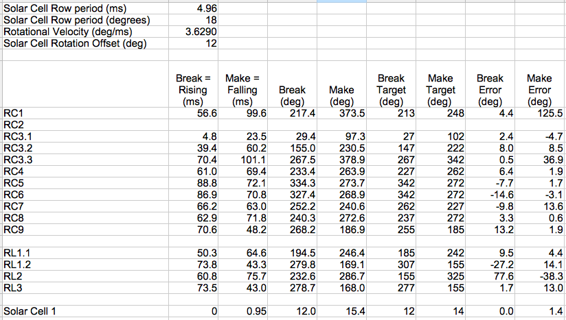
I used the Solar Cell to trigger the scope, then used the scope cursors to measure the time to the various make and break signals. Because I know the theoretical angular spacing between them, I used the time between the first two solar cell pulses to calculate the machines actual rotational speed, which I then used to convert the scope time event measurements into machine degrees. The "target" values were pulled from the timing diagrams in the schematics, and the Error values are the differences between target and the actual event angles. You can see that some of error values are huge whereas most are not. I think there are a couple of factors to explain this. One is that a small error in the velocity calculation can translate to a fairly large error in calculated event angle. You can see that even the solar cell pulse itself (bottom row) has appreciable error. Second, the cam signals are often qualified by other signals, either cams or relays. In fact, several of the cam waveforms show only one make/break event pair per cycle, even though they are 3-lobe cams. Without electrically isolating each cam and driving it with a steady-state bias voltage, the cam terminal waveforms do not always show the make and break events of the cam itself. So we will need to dive a little deeper into these cam waveforms, possibly adding a small bias voltage to help reveal the actual cam events. That might just warrant me getting that new scope...
Tape Emulator PC:
I found and and dismantled the PC we use for the tape emulator, and will order and install replacement motherboard caps for the ones that are obviously failing. Shmuel agreed to image the drive for safety, so I left it on the "relay" workbench.
I also had time to open the Tek 465 scope in the workshop to find out why its DM44 voltmeter option's LED display isn't working. But when I measured +12.8 volts on the +5V rail of the LED driver, I gave up. The (evidently shorted) regulator responsible for that rail is somewhere deep in the scope, so it would take more time to fix than I had available. Also, since the scope itself is working, I felt that it wasn't worth the risk of breaking it in an effort to fix the voltmeter. We have other voltmeters.
That's it for this week.
DC
|
- from John Howard
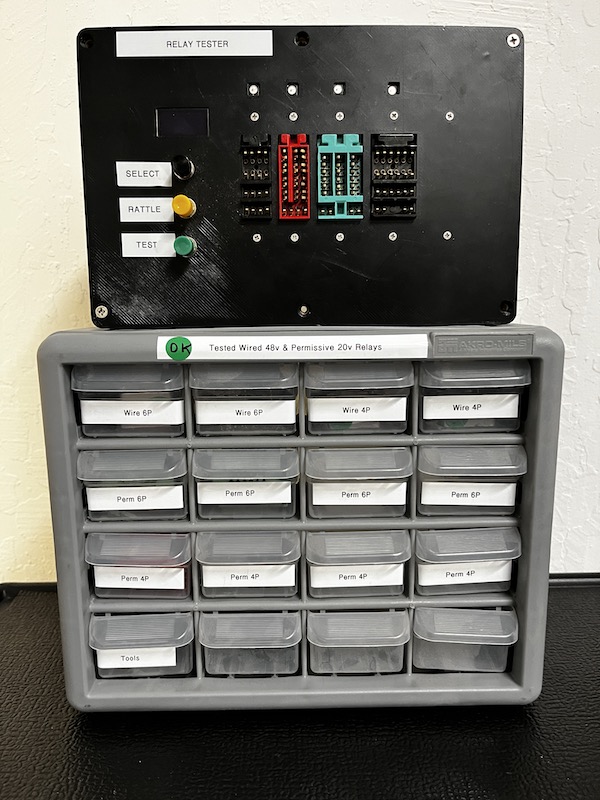
Last week we used most of our restored permissive make relays during the 1402 debug.
This week I started the process of repairing and QAing the remaining 17 spares.
John
|
- from David Clementson
|
Nice work, John!
Just like we have now pretty much eliminated 1402 relay problems by refurbishing and carefully testing them all, I'd like to propose we undertake a similar effort on the cams. I'm thinking that a good strategy for that would be to one-by-one disconnect and isolate each cam (with the unit powered off, of course) and use the milliohm meter to check their contact resistances, and at the same time note their make and break angles using the degree scale on the Dynamic timer. There are about 12 cams to be checked, so even with a few of us working, it will take several hours to complete the task. So let's find a time when both the machine and the milliohmmeter are free and schedule this task. I'd also recommend that we go ahead and replace the solar cell code wheel because we can, and then re-time it against the brushes. We have not checked brush timing in months. For that we'll need the digital scope. It would probably be best to hold off on this task while Ken works on the DE 1401 parity issue, since he'll need the scope for that. Fixing DE's parity is certainly a higher priority.
DC
|
- from Frank King
|
Good Idea David. Now that I have found a group of plug wires that fit the timer that should make an isolated cam circuit breaker easy to check the timing using the timer built into the 1402. We can test that next Wednesday.
Frank
|
- from Ken Shirriff
|
>> For that we'll need the digital scope. It would probably be best to hold off on this task while Ken works on the DE 1401 parity issue, since he'll need the scope for that.
I brought in my scope, so we can work on both problems without scope contention.
Ken
|
- from Samuel Shottan
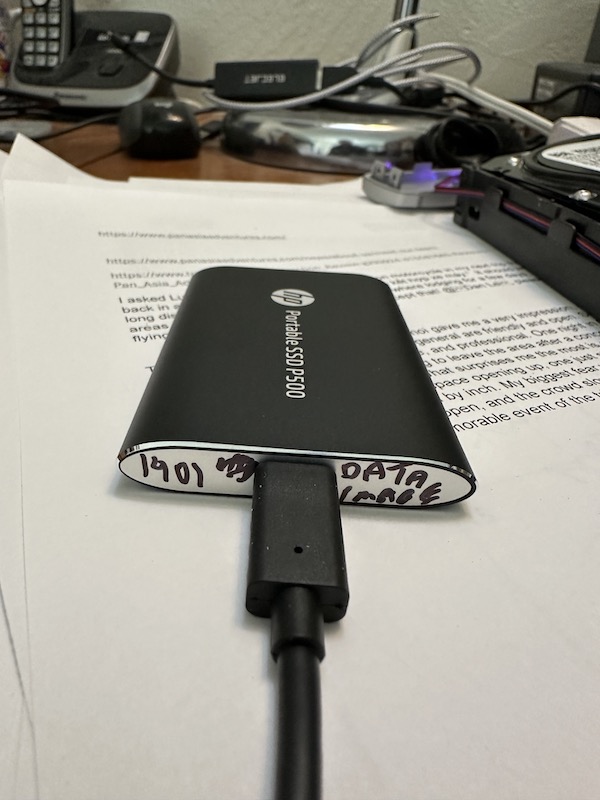
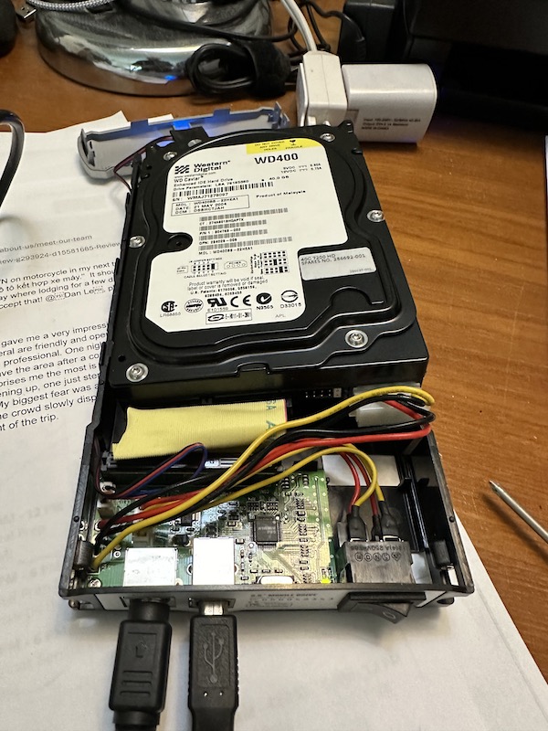
Following up on: " Shmuel agreed to image the drive for safety, so I left it on the "relay" workbench.".
Done.
- Instrumentation: IDE to USB (pic attached).
- As expected file system copy resulted in lacking read permissions to certain directories. Avoided any changes since would have changed the disk image, and assuming David repairs the motherboard it should just boot and work properly. (see attached PDF for file system content)
- Created two (2) disk images:
(a) bootable on any Windows system
(b) Data image only (none bootable) for ability to transfer bit image to any media.
Each image is on a SSD drive (see pic)
Will leave all back on the relay repair station on Saturday.
Best regards,
Shmuel Shottan
If you aren't able to repair the motherboard readily, I should be able to make a new image and make use of a hardware abstraction layer version that can be booted/cloned to any hardware and made bootable. :)
Likewise, if you can't remember the credentials, I oughta be able to bypass/crack those also,
~Samuel
|
|
1/6/2024 Mini Restoration Status~ from Samuel Plainfield
|
The museum was very busy this Saturday; the additional assistance provided by Michelle Yu was a big help keeping things moving along swiftly. Thank you, Michelle!
Jack and I spent some time trying to see if we could glean any insights into DE's woes before the 1pm demo. I noted that in attempting to LOAD a deck such as BigPrint, the CPU was responding with a repeatable error that typically occurs only when the cards are out of sequence (the Check Reset light illuminating and myriad errors in connection with Process and Storage, etc.)
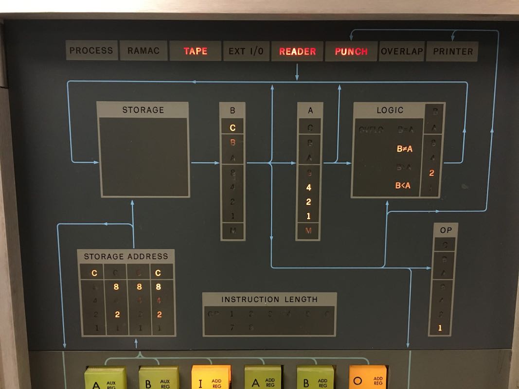
So, in order to rule things out more scientifically, I flooded the memory with zeros (just a check-bit, nothing else). Then, I attempted to load just the 80-80 List single-card program and nothing else. What occurred multiple times was: (1) the punch check would illuminate right away; (2) the reader check would illuminate; but (3) the card itself had not even touched the read-check brushes.
A reader-check cannot occur without the card passing both sets of brushes. Here is the position of the card during the error:
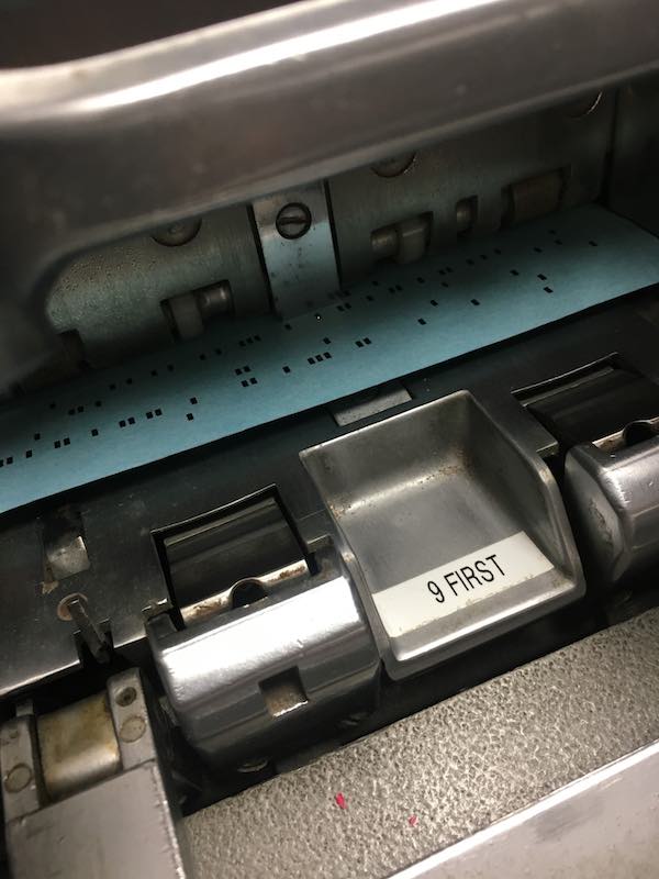
If you look on the CPU, you'll note that there is 4 2 1 data/character indicated in address register A. Since I flooded the memory with zeros... where did 4 2 1 come from? I suspect that this has to do with the CPU believing it is receiving data in connection with the punch side of things. It is my hope that this is a helpful clue for next week.
In addition to the 4 2 1 data/character, I also noted a lone A data/character would appear sometimes in the same register.
CT performed brilliantly for the remainder of the day and there were at least 70+ more guests from the end of the demo until the museum closed.
~Samuel Plainfield
|
CHM 1401 Demo Sat 01/06/2024
11:00 AM - from Jack Ghiselli
|
I thought I'd try Larry Hara's suggested tabular form for demo reporting. Does this work for people? Red indicates things that need attention,
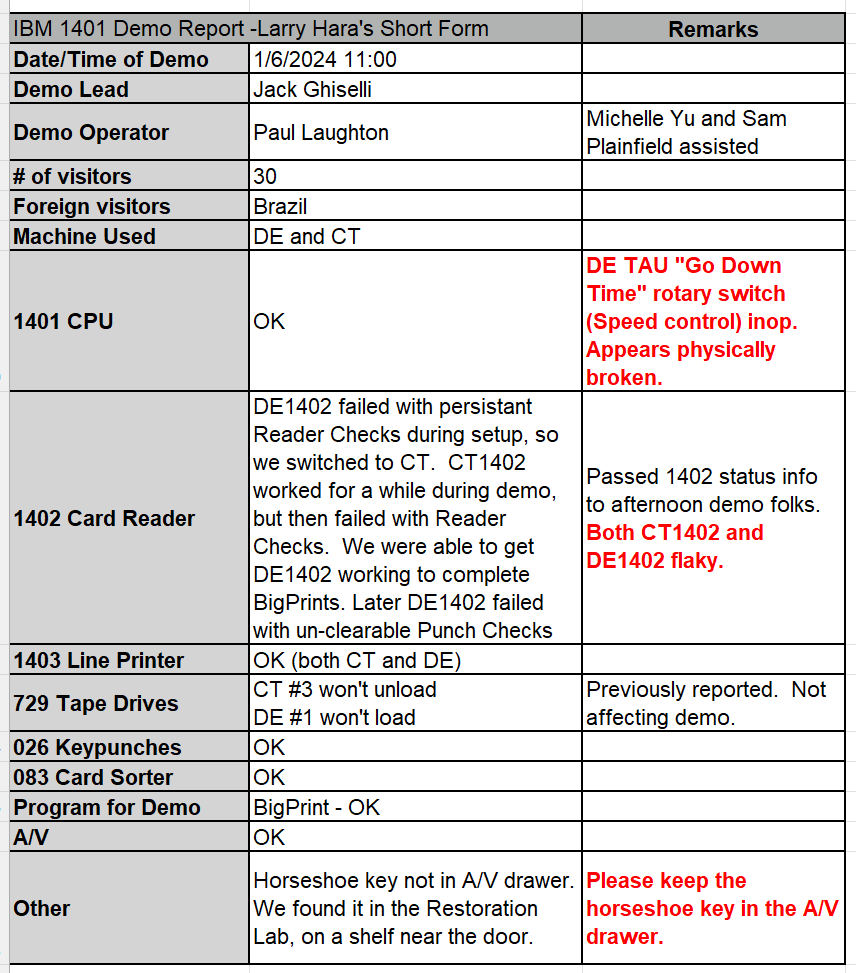
Jack Ghiselli
jghiselli@sbcglobal.net mobile 1-408-839-1051
comment from David Clementson
I very much like the tabular format since it makes it easy to visualize the health of the individual system components. The color coding is a nice touch! It would be even more useful to have separate cells for the DE and CT components to help us prioritize our repair work.
DC
- comment by Larry Hara
I originally had separate columns for CT and DE but thought it was cumbersome. If others like this format, I’ll redo it in to make it easier for the Lead to write and for this distribution to read with special consideration for the Restoration Team.
Not sure if we need to standardize on a format though. Could be a Lead’s choice.
Larry
|
- from Jim Maurer, the 1 PM demo
|
On January 6, 2024 I was the lead for the 1 pm demo. Sam Plainfield was the operator. Michelle Yu was the backup operator. There were 65 visitors counted. Foreign visitors came from Canada, Ecuador, Germany and New Zealand. There were visitors who came in afterwards, but I don't have a count.
All 3 keypunches were used. The printing from #2 was light.
CT was used. There were a few read checks, but I don't believe there were any other problems with the 1402. Tape drives 1, 2 and 4 were used with no problems.
Jim Maurer
|
|
IBM 1401 Demo Status - 1/3/2024 - from Pat Buder
from Pat Buder
On Wednesday, January 3, 2024, Scott Stauter and I gave the demo to
another large holiday crowd. Jack Ghiselli was the backup operator.
Initially there were 78 guests in the room. However, early in the demo
the 2:00 pm Revolution Tour docent brought in another several dozen.
Another 21 came by before or after the demo. The visitors were from
Canada, Japan, El Salvador, Colombia, Argentina, and other places.
IBM 026 keypunches #1 and #3 worked well; #2 printing was very light
despite an effort to reverse the ribbon direction and advance it well
past the initial segment. Both microphones worked reasonably well.
While setting up before the demo we found that DE tape drive #1 wouldn't
load. #2 had tape jammed in the supply reel. Jack and Scott cut off the
damaged tape and applied a new load point marker. We prepared two tapes
on CT and Scott used them for the demo. Given the large crowd there was
no possibility of moving them from DE to CT for the tape demo. I pointed
to parts on a drive on DE as Scott explained them so that that half of
the room could see better.
We ran most of the demo on DE. It ran BigPrint fine. For the tapes, we
elected to use the CT drives.
Pat
|
|
Restoration Report for Jan 3, 2024
from David Clementson
|
CT 1402 card munching, yet again:
Reports from the demos continue to indicate that the CT 1402 has relapsed into its old habit of mutilating cards. So we set about to find out why.
I tried the familiar test whereby a NPRO is initiated with Card Lever #1 depressed and discovered that unlike the DE machine, CT no longer exhibits the expected repetitive clutching behavior, but instead runs one and only one clutch cycle during the NPRO. The lack of this repetitive clutch behavior has correlated with card mangling in the past, and although it is by no means a definitive test, it is all we have to go on to track down the card mangling problem. And it is a realistic expectation that the machine would need to run multiple clutch cycles in order to purge its entire card path.
We began by replacing relay after relay with ones that had been refurbished and certified using John's new milliohmmeter. After replacing all of the relays that seemed relevant to card transportation (Arda has the list,) the behavior was unchanged. So we changed tack and started looking at the clutch handshake signals at the 1401. The idea is that if we can figure out which signal actually kicks off the first clutch cycle, we might see if it is also supposed to start the (missing) subsequent clutch cycles. Arda has come up to speed on mapping the location of signal nodes inside the 1401, so he was able to put a scope on the 1401's clutch drive output signal -T READ CLUTCH, and some of the 1402 output signals we suspect instigate NPRO clutch cycles. We were able to observe activity on -T NON PROC FEED and -T RD COMP GATE, but -T READ CLUTCH showed activity before there was any activity on either of those two lines. So there must be some other signal/event that causes the initial activity on the clutch drive signal, or else we somehow missed the initiating event on the signals we looked at.
Unfortunately, we ran out of time to finish this experiment, so hopefully we can do that next week.
In parallel, I set about trying to verify the cam signals for both timing and signal integrity. However I was only able to discover that our Tek 2230 storage scope on the cart needs repair: in 2-channel mode, it adds Channel 1 and Channel 2 despite the position of the Add/Alt/Chop switch. Verifying the clutch signals almost requires the use of a storage scope, so we'll need to schedule this effort around the availability of our modern digital scope. Or maybe this is the excuse I need to buy one of the spiffy new Rygol DHO804s I've had my eye on.
Finally, I had a thought that we may be able to easily and non-invasively determine the state of a relay by probing its magnetic field. Sure enough, when I placed a SS41 Hall Effect sensor near the center of a relay's coil on the bench, it reliably indicated the state of the relay. This would be an ideal way to determine the state of a relay because it provides a fast, isolated, TTL-compatible signal compatible with modern test equipment.
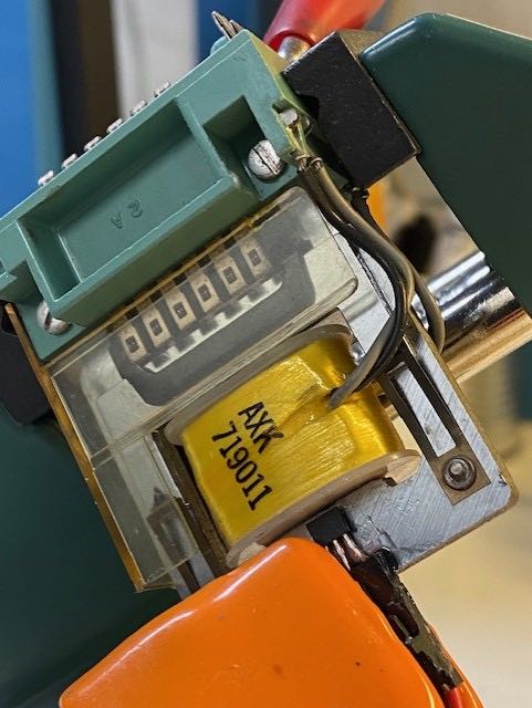
In the photo you can see the sensor peeking out from beneath the orange spring clamp (the clamp being necessary because our instant glue is anything but instant.) I haven't checked if both pick and hold coil energization can be sensed, but the odds are pretty good that we can find a sensor that can. If this works, we could add sensors to all of the relays and connect the TTL signals to a conventional logic analyzer (which I believe we have). We could then record different card processing sequences, and compare the CT and DE machines' relay signatures for consistency. Similarly, adding opto-isolated metrology to the cam signals and the three card levers would allow us to monitor and log the machine's complete state. Having a complete state transition map would be a huge benefit to understanding not only how the machine works, but what is happening when it doesn't.
I also discovered that the Tek 465 scope in our workshop actually functions, although its DM44 voltmeter seems to be broken. So I put it atop the bench where John has been testing relays. And the other two scopes in the workshop are toast.
That's it for this week.
DC
|
- from Ken Shirriff
|
Summary: problems, no solutions.
I looked at the DE 729#1 failure to load. (Symptom: when you press Load/Rewind, the prolay clicks but nothing else happens.) Last year, Marc and I found it suspicious that relay 109 is non-latching, since it is latching in all the other relay 729s. I found the manual for this specific drive and it turns out that this drive has a slightly different circuit for no apparent reason and the relay is supposed to be non-latching, so the relay is correct. The problem appears to be that R109 is not getting dropped, blocking the vacuum pump from starting. It looks like R102 needs to drop, but I didn't investigate further because the punch check returned.
Punch check: DE kept getting punch check errors when reading cards. This is different from the previous punch check in two ways: First, this punch check can be reset. Second, this punch check is accompanied by lots of error lights: reader check, storage check, overlap check. So something seems to be going catastrophically wrong. I started measuring signals with the oscilloscope but didn't get too far before the punch check disappeared and BigPrint ran successfully. Hopefully DE will keep working for the demo.
Ken
|
|
Send comments etc. to ed@ed-thelen.org


 Karen Sun, 11:00AM