return to main page

Tricks for Capacitors


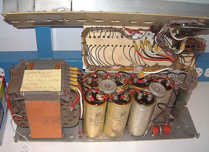
Our sickest power supply

Primarily about "reforming" and testing electrolytic capacitors

Table of Contents


An Interim Report by Ed Thelen, August 2006
I suggest replacing old high voltage (greater than 400 volts?) electrolytic capacitors.
Gory details here ;-))

We have not completed testing/reforming all the electrolytic capacitors in the 1401 system. (We have not processed the last three of the five 729 tape drives so this is not a "final report". We are working on the mechanical issues as higher priority than electrical issues.)

However - I have formed some definite opinions about the characteristics of long unused (no voltage applied) electrolytic capacitors in this 1401, and likely other industrial electrolytic capacitors of the 1960s and 1970s.


"Executive Summary"

The 1401 system had not been powered up for at least 20 years, and we worried about the electrolytic capacitors.

Of over 100 capacitors tested, none failed nominal testing.

"Higher voltage" electrolytic capacitors (say over 70 volts) take a lot more "reforming" than "low voltage" electrolytics.


Gory Details

  • Ron Williams made a nice 30 volt unit with a low wattage electric light as a current limiter, as per various Internet sites. Hmmmm - no picture? This was useful in testing/reforming the capacitors in the power supplies in the 1401 itself. See 1401 capacitors.

    It was difficult to distinguish the normal inrush current into a capacitor, from any reforming action that might be occurring. The current limiter lamp seemed to glow in about the same time pattern with both long unused and recently used capacitors. It seemed that these low voltage capacitors were relatively well formed.

    There were several capacitors that had oozed in service, and the results were now hardened - presumably by evaporation. These units tested as working, and are actually in service in the 1401 now.

    We tested each capacitor for at least rated capacitance at rated voltage by watching its discharge curve through a known resistance.

    (The manufacturing tolerance of electrolytics is typically -10% to +90% nominal. None were found less than +5% rated capacitance.)

    We also tested each capacitor for internal leakage by charging the capacitor up to rated working voltage, letting it soak for maybe 30 seconds, then watching its discharge curve through the usual voltmeter 10 meg-ohm resistance. If it seemed to be less than 5% in about 60 seconds we figured it OK.

  • There was a fuse blowing situation in a 026 key punch donated by someone in Morgan Hill. We found an electrolytic capacitor, reformed it, and the fuse blowing went away and we could get on with trying to make the rest of the 026 work. (Jan 22nd, 2005) That capacitor took about a minute to reform through a 4 watt 120 volt light bulb.

    We forgot to re-form a 5400 ufd 50/60 volt capacitor in a 077 collator. The capacitor got damaged and needed replacement (Wednesday May 11, 2005) (Who ever had installed that power supply also disabled its circuit breakers!)

  • To handle the higher voltage capacitors, for instance the 60 volt power supply for the printer hammers, Ed Thelen then made a unit with a VARIAC (continuously variable transformer) and a low wattage lamp current limiter, and a switchable discharge to facilitate measuring the effective capacitance. (fewer clip lead changes ;-)) Thankfully no picture ;-))

    Using the above variable voltage system we tested/reformed a number of low voltage (below 30 volt working) and higher voltage (up to 170 volt working in a 729 tape drive) capacitors.

    The 60 volt capacitors seemed to take about 2 times the normal inrush current to begin normal function, and the 170 volt capacitor seemed to take 15 or 20 times the normal inrush current to reach normal working voltage.

    Capacity and leakage of all tested capacitors seemed reasonable.

  • Grant Saviers later got us a capacitor tester that also tested ESR, (Effective Series Resistance). See Wednesday September 7th report on main page.

    We have not used this since the capacitors seem to be working well, and run at about ambient temperature (they do not get noticeably warm from their ESR, so we assume their ESR values are well with in requirements.

When we start testing the remaining four 729 tape drives, ideally we will more exactly determine

a) normal inrush coulombs vs excess coulombs that may be reforming the capacitors, in the various capacitance and voltage ratings.
b) ESR of the capacitors.
and provide more interesting details.

--Ed Thelen, October 18, 2005


Bob Lash to Robert Garner

Capacitor Reforming - August 30, 2004
----- Original Message ----- From: "Bob Lash" < bob@bambi.net >
> Hi Robert -
>
> From what I understand, once a cap is reformed
> sufficiently to be back within the manufacturer's
> maximum rated leakage for new parts, and is put
> back into use, the capacitor will continue to
> "reform" from normal usage. So I would expect these
> caps to generally become "better" in leakage
> characteristics as long as they are used frequently
> going forward. This factor (along with avoiding excessive
> ambient heat) will probably have the largest impact on
> the long-term performance of the parts.
>
> See you Tuesday!
>
> Best wishes,
>
> Bob
 
From Ed Thelen < ed@ed-thelen.org >

The above is identical with my "impression".

(knowledge is too strong a word by far)

Robert -

Does your capacitance meter measure ESR
(Effective Series Resistance)?
This is an interesting parameter that might be more
useful than a marginal electrical leakage -


A commercial ESR testing unit

"CapAnalyzer 88A Series II"
is available for $200 at
www.newark.com/NewarkWebCommerce/newark/en_US/support/catalog/productDetail.jsp?id=96B1905

Robert mentioned that it would be nice to find diagnostic tests/information predictive of early end-of-life of electrolytic capacitors.

Anyone hear of such?

Also, a presentation about the 2002 Taiwanese capacitor problem is here

http://www.niccomp.com/taiwanlowesr.htm
where someone blew-it on the magic elixir electrolyte.

Cheers

Ed Thelen
Robert Garner responded
 The Sencor tester I brought in does not test ESR.

As the web site noted, a signal generator and scope is
sufficient.  (But should use sine, not square waves.)

Could also check several/many different frequencies,
a full frequency response being ideal.
Question with ESR is what are acceptable values
for the particular cap.
Mike Cheponis responded
FWIW, we completely ignored ESR in our measurements.
We did consider capturing it, but the additional complexity
/ time versus useful information didn't seem worth it.

After all, these caps are, for the most part,
    in full-wave linear power supplies.

This means they see smooth 120 Hz cosine waves applied
    to them during operation.
...

A long response to short questions - Feb 2006

----- Original Message -----
From: Henk Stegeman
To: Ed Thelen
Sent: Wednesday, February 15, 2006 12:14 AM
Subject: Reforming electrolytic capacitors


> Hi Ed,

> How are you and the 1401 project doing ?

Somewhere about 50% up to running w/o tapes -
http://www.ed-thelen.org/1401Project/CurrentStatusReport.html

   Lots working, lots not -
    the current struggle is apparently with an installed
       instruction/i/o overlap feature that is
           - complex, touching lots of the 1401 parts
           - uncommon - our experts are not familiar with it


> I believe you are the specialist on reforming capacitors.

I've had more experience than most  :-))

> I bought a second IBM S/3 in Germany and this one has
> been out of action for at least 20 years.

Ah, how interesting :-))

> See: http://home.hccnet.nl/h.j.stegeman/PIC00014s.jpg

  BEAUTIFUL !!!

  Do you have any restoration tales?

> It's capacitors might need reforming.

And indeed, in my experience,
    the medium voltage electrolytics (say 25 to say 60 volts)
        probably could use some care in starting
    and the high voltage electrolytics (say 75 to say 300 volts)
        *definitely* require some care.

http://www.ed-thelen.org/1401Project/ActivityReport-Jul-23.html
http://www.ed-thelen.org/1401Project/ActivityReport-Aug-04.html

> I have some questions about reforming electrolytic capacitors
> and hopefully you can shine some light on them.

I suspect an electro-chemist could give some theoretical comments,
   and I can give you some practical "light"  ;-))

> Q1: what is exactly the issue with these old unused capacitors ?

In *practice*, at least my experience with the capacitors bought
in the late 1950s, the ability of the high voltage capacitors
to have high electrical resistance to DC current
   at rated working and maximum voltage virtually disappears -
until some controlled current in applied for a while.

This application of controlled current can be called "reforming"
   mimicking the manufacturing "forming" process
   of electrolytics in the 1950s
  I have no idea what the manufacturing process is currently.

> Q2: what happens when reforming ?

I am told that one surface of the polarized aluminum foil
    develops an increasingly thick insulating (dielectric) layer,
    increasing its ability to withstand voltage across the layer.
Apparently as the coulomb per square surface through the capacitor
    increases, so does the thickness of the dielectric,
    and so does the voltage rating.  :-))

And of course, the thicker the dielectric per square surface,
    the lower the capacitance per square surface.  :-((

I understand that the major differences of low and high voltage
    rated capacitors is the


> Q3: what are the consequences if I don't reform them first ?

In my experience with low voltage rated electrolytics,
     - not electrically stressed for about 20 years,
     - say below 20 volts working,
  you might not notice much difference.
   Maybe some increase in inrush current the first time energized,
    then normal performance

We wanted to test the power supplies anyway,
   using current limiting say 7 watt incandescent  lamps

At the beginning I used a continuously  variable transformer,
   but everything seemed normal.

So I eventually skipped the transformer and used a 7 watt
    incandescent  lamp in series with the power cord.

With medium voltage and high power supplies,
  I eventually stayed with the series lamp resistance -
   but you could definitely see the lamp stay bright
   for much longer times with the higher voltage capacitors.


> Q4: was reforming really needed with the 1401 electrolytic capacitors ?


There are folk lore stories of exploding capacitors.
The tales of manufacturing folks expressed that lots of heat
and be generated during the forming (and "reforming")
potentially vaporizing the electrolyte (steam!!) and
the resulting internal and external damage.

I can add a folk tale.  We have an 026 key punch that was
unused in a garage for many years. We turned it on.
Nothing visible happened - Hmmmm
Checking about we found an open fuse, replaced it.
Turned on the 026 - nothing - and the new fuse was open.

Bother - some darned short !!

Then we spotted a 300 volt electrolytic capacitor in there.
Hmmmm - could that be it??

Disconnected the capacitor and inserted a 7 watt lamp in series
with 100 volts DC.  Lamp glowed brightly for maybe 30 seconds,
then slowly turned dull red, then on light.
Hmmmm - we discharged the capacitor and tried again -
   this time normal appearing inrush current making a brief
   flash, then OK  :-))
We increased the voltage sequence to about 300 volts,
   with the "reforming" apparent at each step.
We re-installed the capacitor into the 026 key punch,
  and no more blown fuses - ever -

> Thanks for time and reply !

Any time -

However, I didn't include in the above the much more extensive
testing of each capacitor for
    - capacity - placing a resistor across each charged capacitor
                  and watching the voltage fall with time,
                  and measuring the time and checking with the
                  expected RC decay

                 ALL capacitors exceeded rated capacity -
                   catalogs express that electrolytics
                   have a capacity range of from +10% to +90% rated.
    - series resistance - placing a 10 meg ohm voltmeter across
                 a charged capacitor and checking that the discharge
                 was slow -

                I was really checking to assure that there would be
                very little DC heating effect which might get exciting.

                I was expecting (and observing) that the apparent DC
                resistance increased with stress time.

Testing omission.
    I did not have an ESR meter available at the time
   http://ed-thelen.org/1401Project/Sched2005July.html
   http://ed-thelen.org/1401Project/ESR-Meter-Doc-.jpg

    So I monitored any heating effect of the completed power supplies
       under rated load for say 10 minutes in still air.
    There was no apparent capacitor heating,
        as tested by touching, in still air
       of any of the capacitors in any of the power supplies.


> Regards Henk


Added comment about electrolytics rated at and used above 350 volts?

I suggest replacing old high voltage (greater than 400 volts?) electrolytic capacitors.

Gory details follow ;-))
I had heard via the Internet that lots of radio restorers recommended replacing electrolytics and not bothering to try to salvage them. Since I was dealing with large, high quality, much lower voltage electrolytics, I could not comment.

I recently purchased an old Pilot tube audio amplifier with a pair of 6L6's with 550 volts on their plates. So I decided to try reforming the electrolytics. The test set up included series light bulbs rated at 110 volts various wattages. I pulled all the tubes except the new Russian 5Y3 rectifier tube (the old one had an open filament). At about 1/3 filament voltage, the 5Y3 was conducting enough to begin charging the capacitors which went slowly to 220 volts. Strange snapping noises came from the chassis, I couldn't figure where - or by what mechanism the snaps would be propagated to the air.

The line fuse was open so I by-passed it. :-||

As I swapped series light bulbs and played series parallel games, I brought the voltage on the filament of the 5Y3 up to 300 volts. The snapping / sparking noises increased in volume/ intensity. The series light would flash briefly at each snap.

At 400 volts on the 5Y3 I concluded that these capacitors were "interesting" - as in "living in interesting times". I decided to continue raising the input voltage to rated but that the electrolytics is this amplifier probably should be changed - but continued increasing the voltage.

I eventually got to 550 volts DC, at almost full line voltage (about 4 volts across the series 100 watt lamp) and let things settle for 10 minutes. I now had a choice of how to test the thing a full line voltage

a) put in a series 12 volt transformer to boost the voltage into a series lamp
b) or guts it - just put the thing across the line - unfused
It was late and I was tired, so I chose b) above.

Across the line, unfused, no series limiting resistance. Indeed, that last step was easy, lets let it soak at that voltage for a while. I turned to other things.

About 10 minutes later, the lights in the room blinked, there was a loud hum from the transformer. As I jerked the line cord out of the socket I noticed the 5Y3 had a violet glow.

Enough excitement - I suggest replacing old high voltage electrolytic capacitors. Don't even bother - I don't know what happened - but once was sufficient.

A sequence of e-mails about Reforming Electrolytic Capacitors July 2015
Eric Smith is a known "good guy" and was involved with reforming capacitors in the
Computer History Museum's PDP-1 in 2003-2004.
He says that their solution (involving "software to control an HP E3631A power supply") was "very over-engineered".
But what do you expect from engineers ;-)))
 ------------------------------

Message: 31
Date: Wed, 29 Jul 2015 01:34:07 -0600
From: Eric Smith 
To: "General Discussion: On-Topic and Off-Topic Posts"

Subject: Reforming capacitors (technical description, not politics)
Message-ID:

Content-Type: text/plain; charset=UTF-8

Some people seem to think that "reforming" an aluminum electrolytic
capacitor is some kind of cheat, akin to zapping NiCd cells or
rejuvenating CRTs. Actually reforming is the same electrochemical
process that the manufacturer uses to "form" the capacitor in the
first place, building up the aluminum oxide layer, before the sheet is
rolled into cylindrical form. The manufacturer typically uses a
forming voltage higher than the rated voltage, from 135% to 200%, to
provide margin for shelf life.

When the capacitor goes unused for an extended time (shelf life), the
oxide layer gradually breaks down, increasing the capacitor's leakage
current and reducing the effective usable voltage of the capacitor,
which is proportional to the minimum oxide thickness. If the oxide has
developed spots that are too thin for the applied voltage, it may be
damaged ("punch-through") when that voltage is applied. Punch-through
tends to be a runaway process, so even a small amount of punch-through
usually completely ruins the capacitor. Reforming the capacitor by
applying current-limited power rebuilds the oxide layer to prevent
this type of damage, and to reduce the leakage current back to within
the specifications. The current limiting is what prevents the
reformation process from causing punch-through and damaging the
capacitor. Many of the capacitor vendors actually publish
recommendations for reforming their capacitors.

See for example information on manufacture on pages 13-14 and a brief
recommendation of reforming procedure on page of 17 of Kemet
publication F3304 dated June 2009:
http://www.kemet.com/ProductCatalog%20Documents/F3304.pdf
Also pages 2-4 on manufacture and page 16 on "recondition" (reform) of
"CDE Aluminum Electrolytic Capacitor Application Guide":
http://www.cde.com/resources/catalogs/AEappGUIDE.pdf
Also pages 1-5 of Nichicon "General Description of Aluminum
Electrolytic Capacitors":
http://www.nichicon.co.jp/english/products/pdf/aluminum.pdf

In at least some aluminum electrolytic capacitor manufacturing
processes, there is actually a reforming step done after assembly, in
addition to the initial forming. See page 9 of the Panasonic
"Aluminum Electrolytic Capacitors Technical Guide", dated April 2013:
http://industrial.panasonic.com/lecs/jp/i/29880/TAL_E/TAL_E.pdf

The reforming process WILL NOT fix other things that may go wrong with
the capacitor, such as failed seals allowing the electrolyte to dry
out, or corrosion, or punch through which can result if the oxide
layer is degraded and voltage is applied without current-limiting.

The US DoD published a technical handbook detailing their policies and
procedures for reforming aluminum electrolytic capacitors that sit in
inventory for years, MIL-HDBK-1131. As of 1999 this is "for guidance
only and should not be cited as a requirement, but the information in
the handbook may be useful in determining or evaluating requirements."
For non-mil-spec capacitors, it recommends inspection and possible
reformation every 3-6 years of shelf storage. It recommends disposal
after 12 years of shelf storage, but AFAICT they're just being
conservative, possibly due in part to not having enough practical
experience with reforming very old capacitors.

Shelf storage is of course equivalent to having the capacitor
in-circuit but unpowered. Having the capacitor powered in circuit for
any significant length of time will reform the oxide to some extent
based on the applied voltage, though not up to original factory spec.

When I reform capacitors myself, I use a reforming voltage of 135% of
the rated voltage. Since I use a suitably low current limit, this has
no significant probability of damaging the capacitor, but as with the
initial factory forming, provides some margin for further shelf life.
In my experience, aluminum electrolytic capacitors in equipment that
has been unpowered for 30 years or more almost always need
reformation, but they almost always meet factory specs (capacitance,
ESR, and leakage at rated voltage) after reformation. Since I don't
tend to restore equipment newer than that, I don't have any empirical
data on how much shelf life they can have without needing reformation.

I'm not particularly advocating for or against reformation, as
compared to replacement. Anyone restoring equipment with electrolytic
capacitors is advised to to read the references and decide for
themselves.

Eric


------------------------------

Message: 55
Date: Wed, 29 Jul 2015 17:10:19 -0500
From: "drlegendre ." 
To: "General Discussion: On-Topic and Off-Topic Posts"

Subject: Re: Reforming capacitors (technical description, not
politics)
Message-ID:

Content-Type: text/plain; charset=UTF-8

Capacitor technology made huge strides in the 1960s and 1970s - and has
continued to advance even to this very day. Parts that were once the size
of a Chicago bratwurst are reduced to the size of the baby gherkins that
garnish them, with better specs across the board. And if you want to count
the "supercaps" (you shouldn't), well, then everyone else might as well go
home now.

Incidentally, what exactly differentiates a computer-grade cap from any
other alum. electrolytic?

@Eric

If you're interested, I have somewhere a document from Mallory - I believe
it may be a hardbound volume, perhaps a catalog - that describes the
evolution of the multi-section aluminum can electrolytic, from the early
versions up through the "EP" (Etched Plate) and finally "FP" (Fabricated
Plate) designs. If you'd like to see it, I'll set it aside the next time I
come across it.


------------------------------

Message: 63
Date: Wed, 29 Jul 2015 16:49:00 -0700
From: Chuck Guzis 
To: General Discussion: On-Topic and Off-Topic Posts

Subject: Re: Reforming capacitors (technical description, not
politics)
Message-ID: <55B9666C.6070901@sydex.com>
Content-Type: text/plain; charset=utf-8; format=flowed

On 07/29/2015 03:39 PM, ben wrote:

> I would guess ripple current.


You got me there--in particular, I've had terrible luck with Sprague
"Long Life Hermetically Sealed" screw-terminal caps. Just about every
single one I've run into has been bone dry. Useless to try to reform
those. Lambda used them extensively in their linear PSUs.

--Chuck


------------------------------

Message: 64
Date: Wed, 29 Jul 2015 20:43:31 -0400
From: Charles Dickman 
To: "General Discussion: On-Topic and Off-Topic Posts"

Subject: Re: Reforming capacitors (technical description, not
politics)
Message-ID:

Content-Type: text/plain; charset=UTF-8

On Wed, Jul 29, 2015 at 3:34 AM, Eric Smith  wrote:
> Some people seem to think that "reforming" an aluminum electrolytic
> capacitor is some kind of cheat, akin to zapping NiCd cells or
> rejuvenating CRTs. Actually reforming is the same electrochemical
> ....

Reforming is standard practice with industrial motor drives.
Manufactures (ABB, Allen-Bradley, Siemens) will require that a drive
that is not powered for a year or more have the DC bus capacitors
reformed or any warrantees could be voided. The procedures they
recommend are very similar to those that have been discussed here. ABB
suggests a 3phase rectifier and current limiting power resistor or a
current limiting DC (1000V) power supply.

-chuck