Reforming Capacitors on the 1401
This report got so long and complex that I offer a Table of Contents.
Well friends - we have all looked at web sites, talked with friends, ... about reforming capacitors.
After playing with the leaked capacitor as related in an e-mail of 7/22/04,
|
- Capacitor reforming -
So I "borrowed" that sick looking ROE brand capacitor
- it also has IBM on the label - maybe made
under contract to IBM
... It seemed to take current reasonably (about 20 milliamps) as I raised the voltage at say 1 volt per second. and in less than a minute - the thing was across 30 volts and drawing no indicated current. Hmmmmm what is the meaning of that? Can't be that good! After fooling around charging and discharging through a 110 volt 7 watt night light - I decided that the thing was acting as a capacitor so decided to measure its capacitance. The capacitance of that sick looking puppy is about 20% above its marked 10,000 microfarads !! It takes about 13 seconds to discharge from 30 volts to 10 volts across a 1,000 ohm resistor. Not that I think that sick looking thing that has oozed in the past all over some wires should go back into that power supply, Anyway, lookin' hopeful |
So, I talked with LaFarr who had reformed a capacitor as part of a small home project. We decided to see if we could get some replacement capacitors at Excess Solutions http://www.excess-solutions.com/ on Brokaw in San Jose and see what we could do with the project's power supplies laying on the work bench at Computer History Museum. (see Activity Report Jul-21
1992 capacitors in this machine??
??? How could a 1992 capacitor be in this ancient 1401???
Then I remembered that Arnold Schweinsberg has said in
an e-mail that he had taken the 1401 to a show in Dortmund.
Maybe Arnold had replaced some capacitors with more recent
production? ???
I called Mike Falarski that LaFarr and I were going to
the CHM and likely going to be in the 1401 room into the evening.
Forming and testing a whole bank at one time :-))
We disconnected the 25 ohm 25 watt bleeder resistor and the
wires leading to the positive side of the capacitor bank.
Using the handy 110 volt 7 watt night light as a current limiter,
we connected my 0-to-30 volt power supply to the now isolated
capacitor bank
OH - in the above circuit, I did not show volt meters monitoring
both the Power Supply voltage and the Capacitor Bank voltage.
And ideally, you should set the voltage of the Power Supply to
the working voltage the Capacitor Bank. Part of the game is to
assure that you don't over voltage the Capacitor Bank much.
If you do, you will reform the capacitors to a higher than necessary working
voltage and reduce their capacitance.
OK - well now - How effective is that capacitor bank?
Lets look at the leakage resistance of the capacitor bank.
I disconnected the 0-30 volt Power Supply and watched the voltage.
The voltage decreased so slowly that I got bored and figured
the leakage resistance was high enough for practical purposes. :-))
I then placed a 10 watt 250 ohm across the charged capacitors.
It took 30 seconds for the voltage across the capacitors
to decrease from 30 volts to 10 volts (about 1 time constant).
Using the formula,
I did not figure an easy way to measure the effective series
resistance of the capacitor bank. A practical evaluation
of acceptable series resistance is to measure the
temperature rise of the capacitors when handling
rated or system current load
The above was very good news:
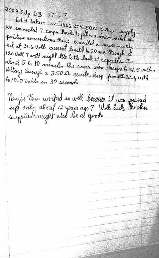
Pictures and log book
Life was good. Lets see if we can do more !!
Excess Solutions had only one 30v capacitor in that form factor
and we bought it. As we checked out, we explained to the clerk
what we were doing and showed him the old oozed capacitor.
He said "This 'old' capacitor is newer than the capacitor
you just bought!" - WHAT? "Yes, look at the date codes,
this 'old' one was made in 1992, and the one you just purchased
was made several years earlier."
LaFarr and I decided to put the 'old' oozed capacitor back
into the power supply and reform all 7 capacitors at once. :-))
Figure 1. Capacitor Charge Circuit
and watched the night light filament glow dull
red and the voltage rise on the capacitor bank. In a short time
the capacitors were at their rated voltage, and the night light
was not glowing. :-)) Lookin' Good :-))
I figured that the capacitance of
the capacitor bank was about 0.12 farads, well above the
rated 0.07 farads. :-))
We left a big note in the power supply and wrote in the 1401 log book.
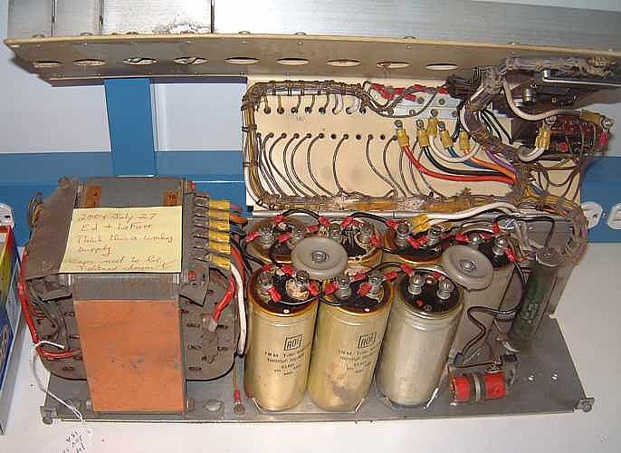
1st Power Supply
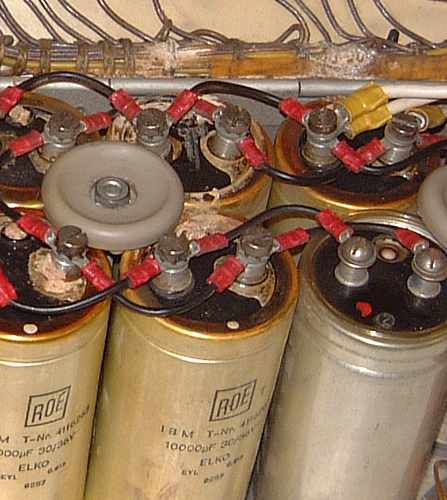
detail of the now solid leakage
And 1401 log book page 2
We did notice that the clamp-downs for the capacitors seemed designed
for *eight* capacitors, and only seven were present. The eighth
position seemed to contain an informal modification. I did not
identify the red thing - but it was wired as part of the capacitor
bank and was so tested.