Schedule September 2006
return to main 1401 Restoration Page
go to Team Bios
- 50 Hz Power is back - preliminary details here. Ron Crane's later report here
Contents:
Wednesday September 06 - general,
Thursday September 07 - Tape Team
Saturday September - 2nd Saturday
Wednesday September 13 - general meeting & work
Since the 1401 CPU opcodes and most of the peripherals are now working (or nearly working), a new objective
is to begin show casing the 1401 to visitors on a regular basis by February(!)--assuming, of course,
that the system proves to be sufficiently stable.
My thought is that demo scripts could be performed say twice a month for ~90 minutes and feature
a running 1401 and some peripherals (026 punch, 1402 card reader, 1403 printer, 729 tape drive).
IBM Almaden Research Center, San Jose, CA
The meeting did happen, and looked like this:
One of the results of the meeting is that Jeff Stutzman "volunteered" to work on the story board of the demo - what a glutton for punishment !!
Here is Robert Garner's Meeting Summary
Those who made it to the 1401 team meeting on Weds deserve an award
for enduring the >one hour, untenable, unexpected traffic snarl
Weds morning
Synopsis of our meeting, after folks were staggering in by ~11:20 am:
Regards,
- Robert
p.s. Footnotes:
After the meeting and lunch (thank you CHM and Jim Somers), many of the group went back to work in the 1401 room. No outstanding
achievements were accomplished :-((
Ron feels it is time for the programmers to wake up and start using the machine.
Module B1 had both .5 amp picofuses (F1A, F1B) open in one amplifier (mounted in lid) open
and limiting its ability to pull to + 100V. After checking transistors and finding them
OK, new fuses were put in and the unit works OK.
Module B2 had one open 2 amp fuse and a shorted transistor (Q19) behind it. While not the
source of the problem, they were replaced. The output would only go partially to + 100V
and then collapse for the rest of the positive half cycle for that amplifier. The problem
was an open 200K 5% pullup resistor R2 (amplifier on bottom of chassis) which was
replaced. Module B2 now works OK.
It was interesting to note that we never saw a neon bulb glowing despite many blown
fuses. We will explore this when going back to look at one of the Phase A amplifiers that
was pulled out last month and had a couple of blown fuses in it. It still worked and may
have been put back in service.
- Ron
Thursday September 14 - Tape Team
Wednesday September 20 - general
This was one of those days that we should have all stayed in bed.
I thought that maybe I could rewind the sick relay coil as I had wound coils for amateur seismometers and started
carefully picking off the nylon protective winding covering the copper wires.
It says that coil 170187 has a resistance of
1145.00 ohms in the pick coil. The hold coil has a resistance of
3200.00 ohms. It says these coils are manufactured to a tolerance of 10%.
I will send you a copy of the chart as soon as I can ...
Van Gardner
Thursday September 21 - Tape Team
Saturday September 23 - 4th Saturday
For the previous 28 months the only people who could usefully keypunch were the exIBM FEs -
who would then hold the card up to the light, squint and peer at the holes to verify what they had key punched.
Wednesday September 27 - general
That little horizontal printer plate adjustment screw is visible and turnable through a special 3/8" hole in the main casting,
but to replace it is a massive dis-assembly job of the heart of a very complex machine.
I am here to tell you that an alarm clock, or watch, is boringly simple compared to the internals of a key punch.
When you take off the covers, you see lots of mechanical assemblies bolted onto the main casting. The read assembly,
the punch assembly, the print assembly, the ribbon assembly, the card movement controls, and on and on.
Each of those assemblies has sub assemblies that are bolted onto the main assembly
Each of those sub assemblies ... and on and on. Like the story of the parasites, the rats have fleas, the fleas have worms,
and those parasites have parasites ... down to protozoa - which may get viri??
What really nailed me was the merging of the interposer sub assembly with some other assembly, and 12 little levers
had to insert into the 12 little interposer slots - all the while trying to work through a 4 inch by 3 inch hole
in the front of the main casting.
Then the kicker was trying to insert two each little sub sub assemblies that looked like 5 inch rulers that were two thin
pieces of metal with six sliding inserts that wanted to separate and fall out - onto the sides of the sides of the
combination sub assembly of the 12 little levers and the 12 little interposer slots - and there was barely
enough room for fingers and light - and then you had to bolt these little ruler looking sub assemblies on -
and ...
And I had forgotten my camera - but it would have taken a third person to operate the camera any way.
The whole experience was like a frustration nightmare.
There has been considerable discussion as to whether we should have had Grant make an 026 replacement adjustment screw -
which seemed to be a "standard" screw with some special groves and things cut into the head - instead of requesting
to get into another keypunch for a replacement.
Thursday September 28 - Tape Team
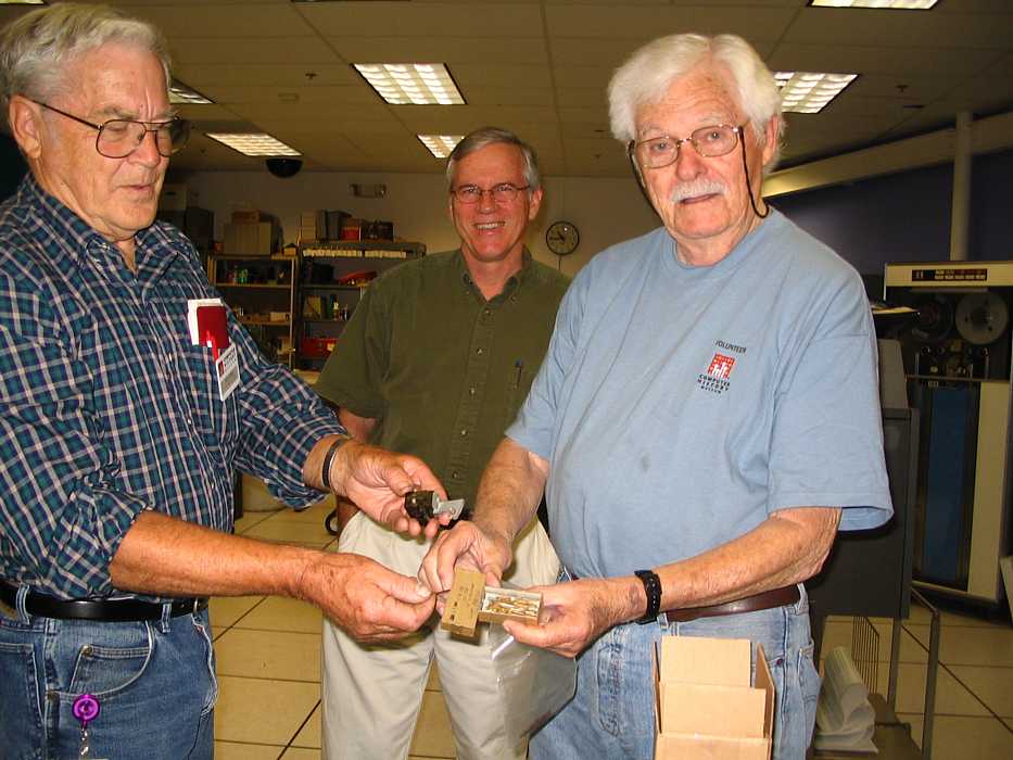
Robert Garner (center) lurks on e-bay, and snaps up specific items we need. Frank King (left) and Bob Erickson
appreciate the 083 sorter brushes that Robert just brought in.

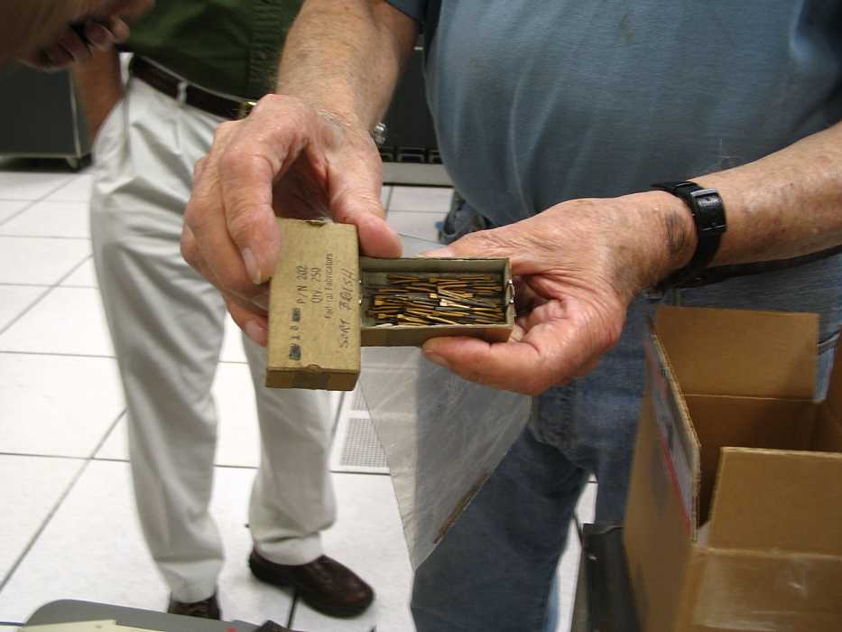
Here is the single brush holder of an 083 sorter removed for brush replacement and length alignment.
Note that the brush alignment "tool" is built into the sorter for easy access :-))
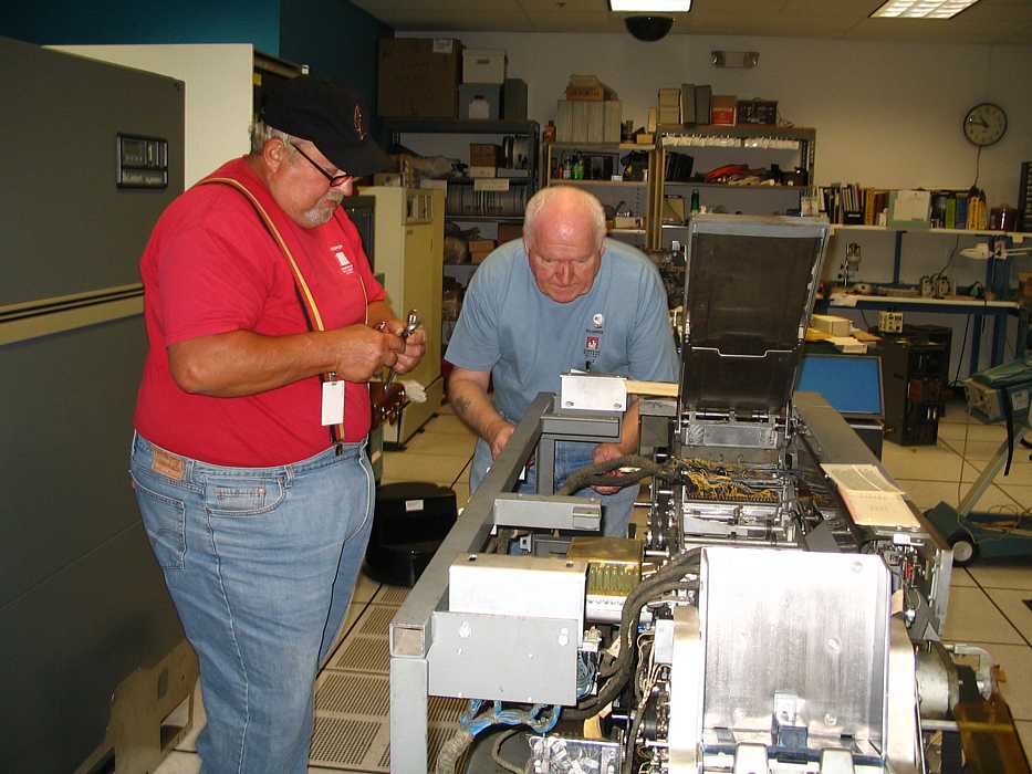
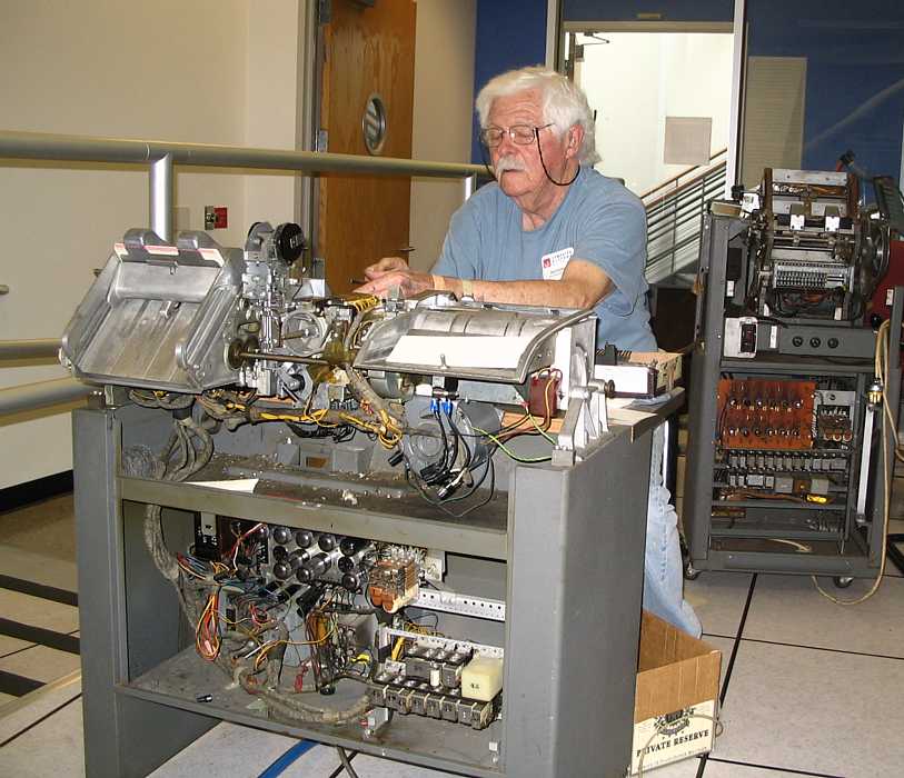
Chuck Kantmann (left) and Bill Flora are re-aligning the timing on the 1402 card reader. It has just successfully
read a large test deck with no read checks - but they think they can do a better job in getting the
adjustments centered. Practice makes purfeckt.

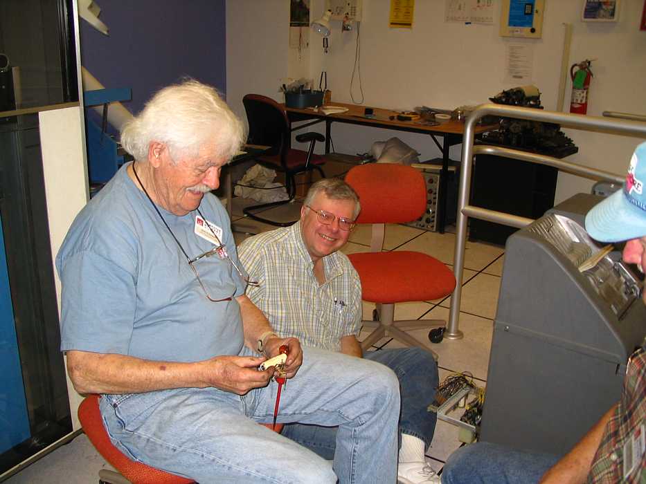
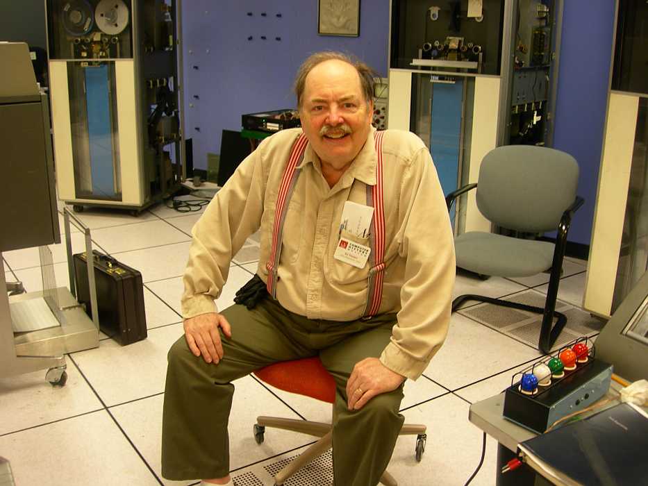
We are in the volunteer lunch room (strangely quite as the staff are not playing cards today). On the left is Ron Crane, the
hero of the day for finding the fault the damaged the 50 Hz converter, reparing the fault, and repairing the converter
(we had been unable to work since August 23 - see here.)
I was AWOL - went to L.A. to sail on the SS Lane Victory -
a WWII Victory ship ( with two boilers and steam turbine drive) I think I saw everything except the bilges,
and the inside of the oil tanks :-)) go-go-go ;-)) - even watched the modern Raytheon X-band radar and saw the modern gyro compass :-))
The following box was the invitation.
Folks,
Our next 1401 all-hands, everyone-invited
meeting will be Weds,
Sept. 13th, 10:30am - 1pm in the Noyce
Conf room.
Jim Somers has indicated that he can
provide a sandwich buffet.
Preliminary Agenda:
For the meeting, please think about possible demo scenarios that would be meaningful and interesting
for visitors and doable by us and possibly by other volunteers and docents.
It will be ideal if someone can volunteer to chair a "demo group": work out a script, work with the Museum
staff, solicit advice from the PDP-1 demo team, write/debug demo software, etc..
It's been over a year since we've gathered to take stock in our progress and look forward. If you have
any suggestions for the agenda, please let me know ahead of time.
I look forward to a concise, productive, and interesting meeting.
Thanks again for volunteering on our extraordinary restoration project!
- Robert
Office: 408-927-1739
Mobile: 408-679-0976
robgarn@us.ibm.com
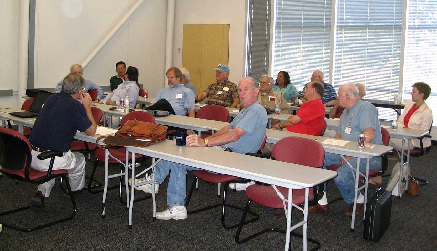
Left to right: Robert Garner (black shirt), Ron Crane, Ron Mak, Jeff Stutzman, Robert Feretich, Bob Erickson (you can see his white hair),
Ron Williams, Glen Lea (he must be thinking deeply, he usually smiles), Frank King (also thinking ;-), lady in green dress helped
the guy in the striped tee shirt), Don Cull, Striped Tee Shirt, Bill Flora, (mostly hidden is Dab NcInnis), and Kristin Abkemeier (who is doing
a write up on why old duffers do this). Not in picture is Ed Thelen (behind camera or looking for food or ...)
Subject: Summary of 1401 team meeting, Weds, Sept 13th. Demo scenarios
And, finally, thanks to Jim Somers for the catered lunch!
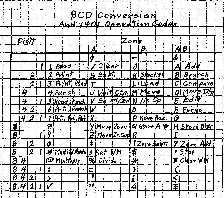
All of the 1401 instructions work (using simple tests). Ron Williams provided this "cheat-sheet" to help coders
punch up cards.
HOWEVER !! Ron Mak's ROPE programming environment works well on your PC
and provides great assembly and program emulation for getting familiar with the 1401 AutoCoder and 1401 instructions.

Ron Crane
provided the following report of his activities in restoring (and improving) the
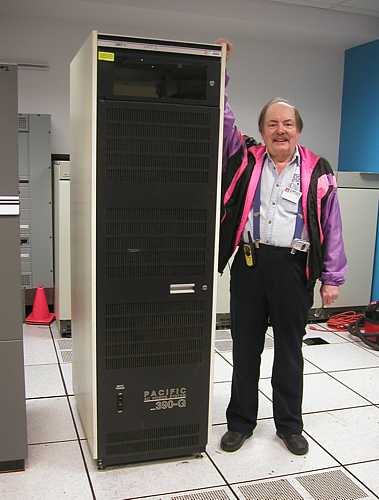
Pacific Power supply we are using to provide 50 Hz power to "our" 1401 computer system.
Jeff [Stutzman] & I completed the basic repair to the unit on Aug. 31, and a few clean up items over
the last two weeks.
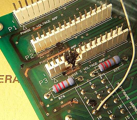
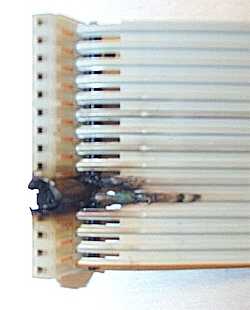
The basic problem was that an IDC connector and pin were burned on the control board
producing smoke, smell, and the unit was shut down. The wire burned because of
overcurrent.

Only the Phase C neutral was connected directly to the load. The neutrals
for Phases A and B were not connected directly in the power box and none of the neutrals
was connected to chassis/60 Hz building ground.
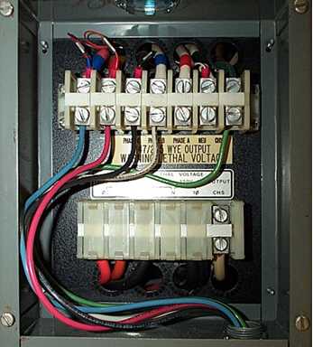
The control board has a signal called
"meter return" which bussed all three neutrals together for a meter circuit. It was this
connection that carried the neutral currents for phases A and B, about 7-10 amperes. It
should be noted that the burned traces in the photographs were already jumpered by 18 AWG
rework wires. Maybe the guys at IBM had the same problem at some point.

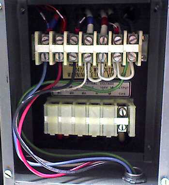
Repair was done by cutting out the burned part of the connector and replacing it with new
parts for both the PCB and 18 AWG IDC connector. To avoid this happening again, all 3
neutrals are connected together and to 60 Hz ground. Before and after photos are
attached. A recommended update for the Pacific Power control board would be to remove pin
6 from the phase B and phase C connectors to the voltage amplifier boards. This would
leave the phase A connection to the meter return.

If the assumption that all neutrals are
connected in the power box were true, metering would work. If the neutrals were not
connected, the load would get no power and the problem would be corrected with no damage
to the control board. We should verify that there is no need for connection of neutrals
at the amplifiers when the output contactor is in the off state.
After bussing the neutrals, the panel voltmeters for Phases B and C could not be adjusted
to the proper value. I investigated only enough to determine that the meters were out of
spec., but seemed stable. The meters are directly connected to neutral and through 40K
1% resistors to each of the phase outputs at the connection box. I took advantage of the
40K series resistors and added shunt resistors (Phase A- none, Phase B-470K, Phase C-697K)
across the phase B and C meters inputs to center the 18 volt adjustment ranges on the
voltage output and adjusted the meter pots to give output readings matching the Fluke
voltmeter. (Meter input resistance was about 1.48M ohm for all 3 meters.)

Two of the phase B output amplifiers (modules 1 and 2) produced only half voltage if run
individually. Together, they produced a full output. Both were necessary to get at least
one good "red" amplifier and one good "black" amplifier for Phase B.
Many tape team members took the day off to shoot fiery objects (rockets) into the sky ;-))
Present were Ron Williams, Don Cull, Bill Flora, Bob Erickson, Robert Garner, Ed Thelen, Tim Coslet, and in mid-afternoon Mike Cheponis
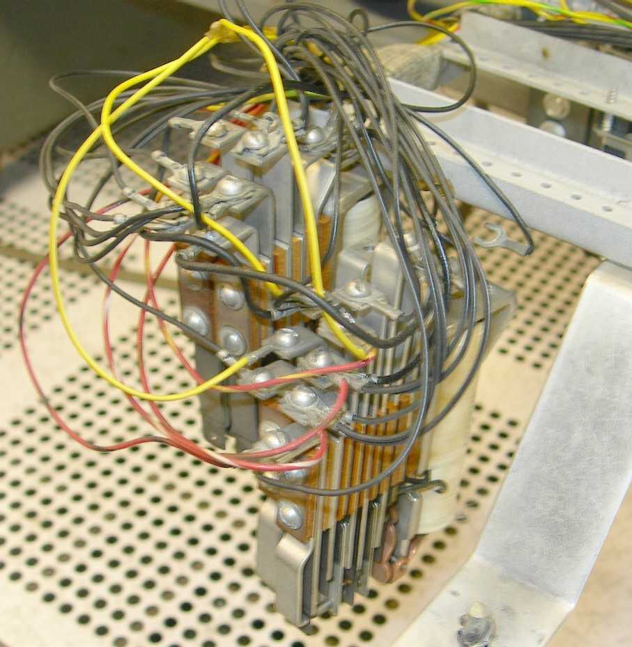
- the "hold" coil in a relay in the loaner (#2) key punch (see August 9)
had been found to be open.
Mike Cheponis (late of the 1620 and PDP-1 restoration projects) showed up and expressed interest in helping
restore the 1401 system. Mike said that his father had rewound coils and medium sized motors in a steel mill in
Pennsylvania many years ago - but Mike was not eager to rewind this coil.
Bob Erickson holding the defective coil, the "hold" winding is open, the "pick" winding measures about 1,200 ohms.
Soon the end of a very thin wire was visible - I had likely broken it in trying to remove the nylon protection.
Others pulled off more wire, and measured it as 0.0031 inches in diameter. Bob Erickson observed that the
average human hair is 0.0025 inch diameter. Mike Cheponis found that the wire was likely
#41 coated wire (see below). Winding #36 wire is interesting enough to hand rewind - is anyone
interesting in trying to rewind a dual wire coil (pick and hold coils) using #41 wire?
This coil is used in a number of relays. (See Red Markings [added])
FWIW, I measured the OD of that magnet wire at 3.15 mils.
My reference book says that the coated diameter of AWG 41 is 3.1 mils
        - so I claim that this wire on the solenoid is #41.
(#40 is 3.5 mils coated, and #42 is 2.8 mils coated.)
Now, back to #41: bare wire is 2.8 mils, so the coating takes (3.1 - 2.8) = .3 mils.
It has 1320 ohms per 1000 feet, and the circular area is 7.84 square mils.
Since one of them was measured at about 1204 ohms,
         that would be 1000 ft / 1320 ohms * 1204 ohms = 775.75757575 feet.
If the resistance of the other coil was about 5 times that, or around 6000 ohms,
         that would be 4545 feet - which seems -way- too long.
-Mike
I just read Wednesday Sept. 20th activity report and remembered that I
have an old 1952 IBM publication Form 22-8788-1.
It has a chart showing the the correct resistance of all the coils used
by IBM at that time.
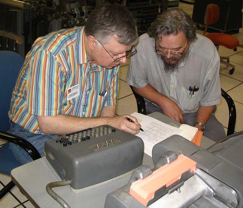
Suddenly Bob Erickson burst out with "I got it"
and presented us with these cards.

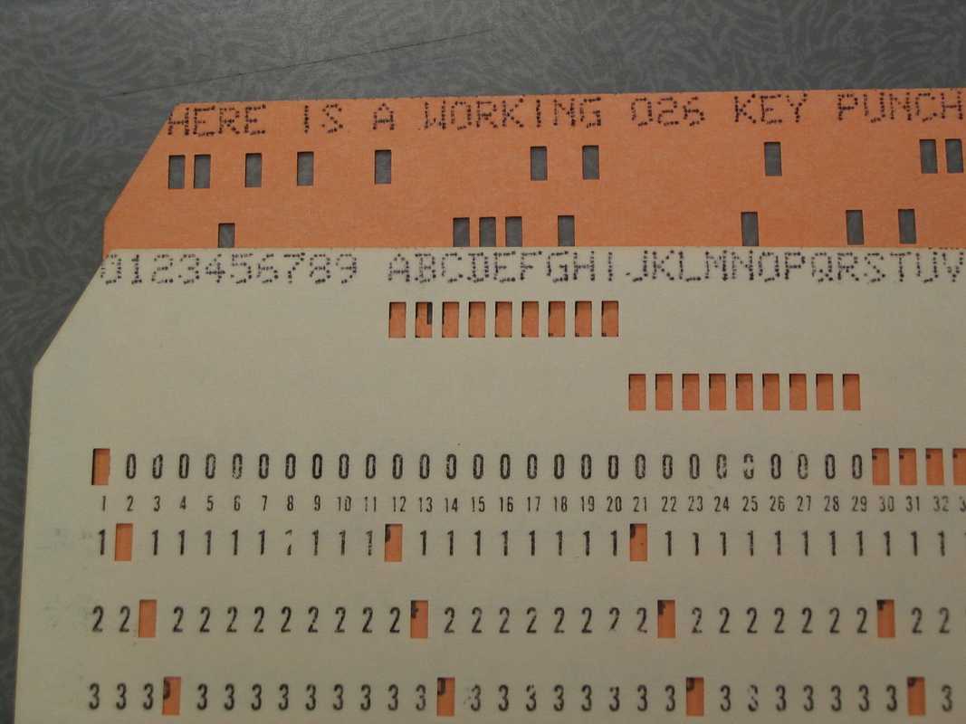
A further close up of some other cards - many of us noted that these were printed more correctly
than many key punches in service in the 1960s :-))

Bob Erickson re-assembling the 026 after the successful punching above :-))


The three complicated boxes on the floor are power supplies for the 3 729 tape drives Mod II and Mod IV.
Ed Thelen connected up a series of resistive loads to the unregulated (actually regulated quite well
by the ferroresonant transformer/regulator) DC voltages. 140 volts, 48 volts and 7.5 volts.
As I was leaving, about 5:30, Mike Cheponis and Tim Coslet were hand encoding a test program
on the newly printing 026 key punch - using an instruction cheat sheet from Ron Williams.
Like most kids, I took an alarm clock apart, and somewhat got it back together again
Maybe we should take a breather and refresh our brains? Take a class in group dynamics - ala Dilbert? Suggestions?
Go to October 2006
go to Team Bios