|
Friday August 18, 2006
A little status report.
I have been a little delinquent in providing update repots on the 729
project. You have not seen me at the CHM for quite awhile as I am still up
at Grant's. We have been rebuilding all the individual clutch reels, the
drive motors & hi-speed rewind motors.
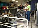
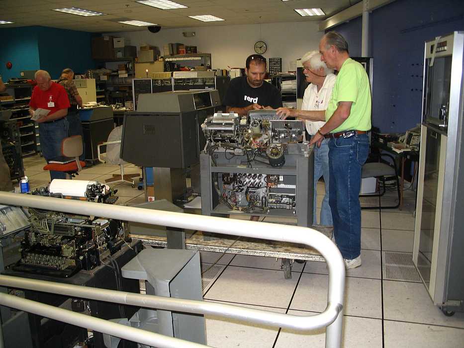
This pass Wednesday 8/16th was great. I arrived at Grant's , and then Bob
followed and later Jeff.
It was decided that we would set up two production lines. One to complete
the clutch units and the other to finish to rebuilding of the drive motors.
Clutch reels.
After working for months we had reached the point where the reel units had
all been all sand blasted, new powder inserted, new inside felt washers
installed and just awaiting the new outside cover plate felt washers.
Punching out the felt washers out of strips of felt was / is not as simple
as one might think. First it has to be a perfect circle and then within that
circle you need to punch out a second perfect circle that is exactly
position in the center of the big felt circle. We had two different sized
felt washers. Grant designed and machined a two-direction punch block. A
strip of felt was inserted, centered over the large cut in the punch block &
then the two sides of the block were bolted together. Then using a hand
press the large punch was pressed through the felt. Then the block was
turned over and a second punch was inserted to take out the center hole and
was driven through the felt. Then the blocks were unbolted, separated and
the washer removed. This was repeated 30 + times with medium weight felt for
set of washers & then 30+ more times again with heavy weight felt. Now all
we needed was to punch out and install the back cover washers.
This past Wednesday we needed to repeat the felt washer process but with a
new punch because we needed the make washes of a different size. Grant
machined the new block & punches. He then started the job of hand punching
out the 30+ felt washers we need while I removed the 'C' clip and brass ring
plate to get to the old washer, removed it, installed the new washer and
reinstalled the brass ring & 'C' clip. We finished them all.
They are now ready to be reinstalled on the clutch shafts into complete
clutch assemblies. That should take a few weeks to complete. Then back to
CHM.
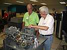
Drive motors.
The drive motors used an 'open faced, grease packed' bearings (2 per motor).
Let us just say that the bearings had served their time. The ten motors (2
per drive) were removed and brought to Grant's where they were stripped
down, cleaned and new bearings installed and then put back together again.
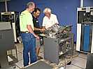
Bob went to work to finish the remaining motors. It was a very dirty job
with oil, grease, dirt, and rubber drive belt slough making for a mess. Bob
put the smaller parts in the ultrasound bath and the motor end bell housing
went into the kerosene greaser. After he had all the parts looking liking
like new, he installed the new sealed bearing and reassembled the motor.
Nine of the ten motors have been completed and the last one will be finished
next week. Jeff helped out wherever an extra pair of hands was needed. And
they were needed.
Hi-speed rewind motors.
There is one per machine and the ModV on the floor has already been rebuilt.
That leaves the four others to be rebuilt. I expect that we can do them is
one workday.
The next problem to be solved (read designed & individually machined) are
the 60 commutator brushes we need ( 2/reel x 3 reels /shaft x 2 shafts /
drive x 5 drives). We can if necessary use the ones we have but it would be
nice to install the new brushes at the same time we are installing the
clutch shafts. Removing & replacing the brush block bracket is very
difficult & time consuming. I have spent move than 1/2 a day with Glenn and
I working together to reinstall one bracket. Not one of IBM's shining design
moments.
And then what?
Like Moses it will be time to come down from the mountain but rather than
bearing two stone tablets we will be bearing 8 completely rebuilt clutch
shafts, 8 shiny drive motors and 4 little but no less important hi-speed
rewind motors plus the items that have already been reinstalled in the Mod V
on the floor. Not a lot to show for 10 months of work in the mountains (so I
took some vacation but who's counting other than Robert) or so it might seem
but a lot a trail and error, testing, machining parts & tools, you name it,
to get this stuff rebuilt.
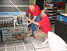
The other ModV has been completely cleaned up, had its power supplied
pulled, tested and reinstalled and needs to have the drive motors, hi-speed
rewind & both clutch shaft reinstalled which will complete the mechanical
rebuilding. This should take abet 2 work sessions. Then we can turn on the
power and see if & how well it executes commands. Time for that - unknown.
Then it's time to cable it to the CPU.
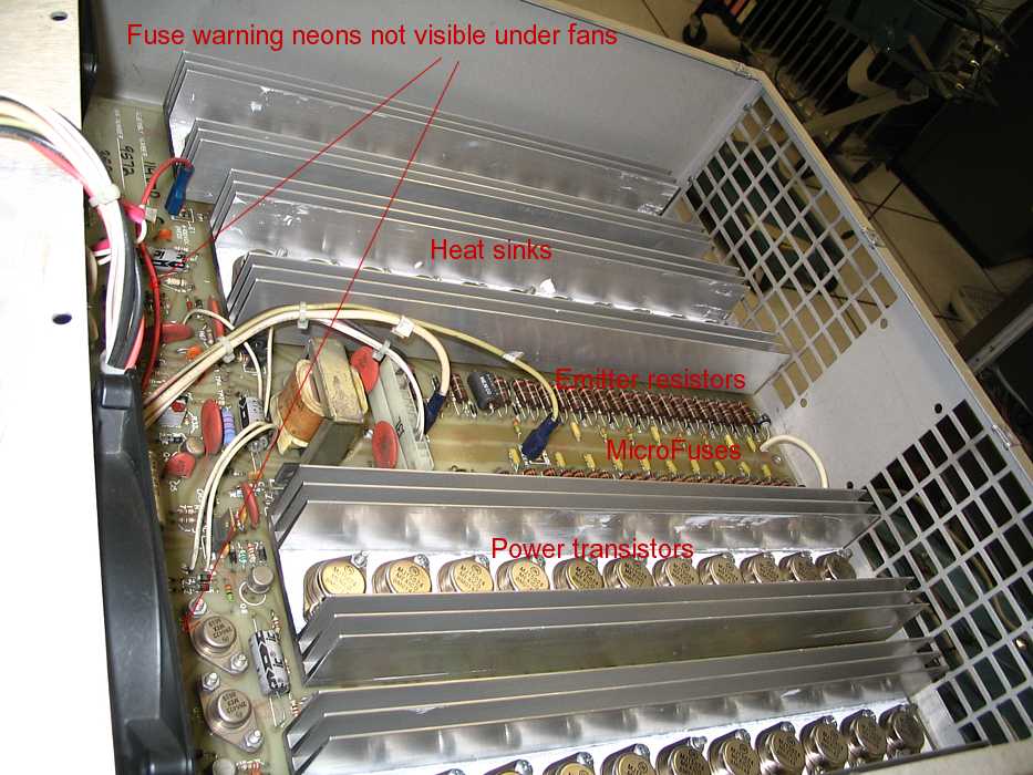
The other 3 drives will follow the same pattern. Their power supplies have
been pulled and have been turned over to our very excellent power supply
rebuilder Capt Ed. The drive frames themselves have not been physically
cleaned but once they are, we will work on them as above. With help we can
work on more than 1 drive at a time. These drives pose the possibility for
greater problems since most of their control circuitry are relays- many
different types - mechanical timers, heavy power driver transistors.
And by February/March '07?
We should have 4 up and running drives. Why not 5 - if we need parts
somebody has to be the donor and why not the 5th drive. I am sure it will
gladly give up its life to save the other four - it's called 'for the
greater good' the same thing government is always saying when it collects
taxes.
This concludes my yearly report and what we have accomplished after two +
years of work.
I knew that taking this as a fixed bid contract was wrong. Mother said 'go
for T&M'. Always listen to mother.
Allen j Palmer
| 

