The 1401 console
from Ken Shirriff - Sept 12, 2015The IBM 1401 doesn't require much console interaction in normal use, but there are some useful things to know about it. The console also provides debugging features.
Default settings
Several console switches must be in the correct positions or else the 1401 will not operate normally. The I/O CHECK STOP toggle and A toggle should be up. The mode switch should be in the RUN position. The TAPE SELECT dial should be in the N (normal) position. On the auxiliary console, the CHECK STOP toggle should be up. The auxiliary mode switch should be set to OFF.
Useful buttons
The POWER ON and POWER OFF buttons turn the 1401 system on and off. The CHECK RESET button lights if there is a fault, and is cleared by pushing the button. The START RESET button resets the system (except for address registers and core).
Console layout
The upper part of the console gives a block diagram of the 1401's logical elements. The B, A, LOGIC, STORAGE ADDRESS and OP blocks are illuminated to show the character value in that component. The LOGIC block also shows comparison status. The INSTRUCTION LENGTH block shows the length of the current instruction. The various labels light up in red if there is a fault in that component.
Each STAR register has an illuminated button. One of the buttons lights up to show which register is being displayed in STORAGE ADDRESS. Below these buttons are MANUAL ADDRESS dials, which can be used to enter an address.
To the right of the address dials is the mode switch, which is very important since it controls the operating mode of the 1401.
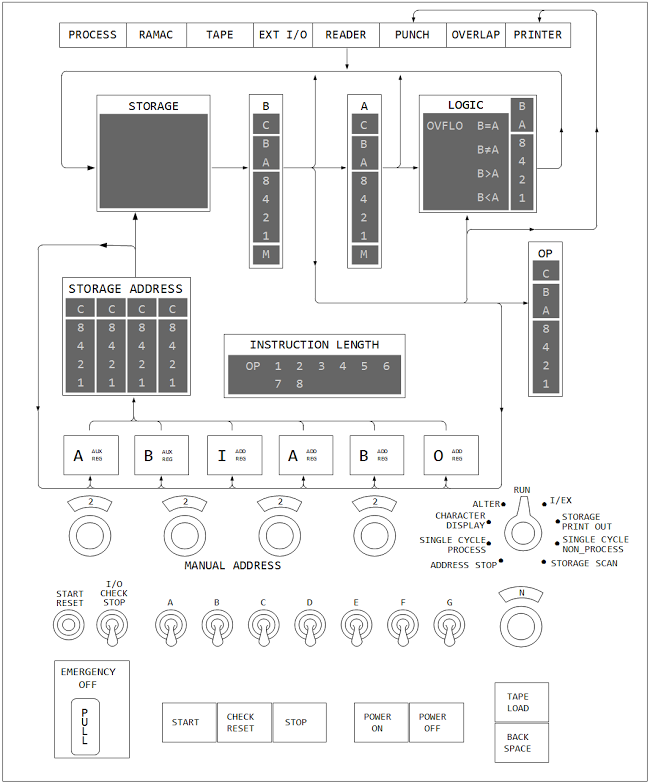
The next line of switches consists of the START RESET button, which resets the system (except for address registers and core); the I/O CHECK STOP toggle, which enables I/O validity checks; the sense switches (switch A enables last card detection); and the tape mode dial.
At the bottom of the main console are the EMERGENCY OFF handle; the START button, which restarts execution; the CHECK RESET button, which lights if there is a fault, and is pressed to reset the fault; the STOP button, which stops execution; the POWER ON and POWER OFF buttons, which turn the entire system on and off; the TAPE LOAD button, which loads a tape; and the BACKSPACE button, which rewinds the tape one record.
Underneath the main console is the auxiliary console, which provides additional controls that are mostly not used in normal operation.
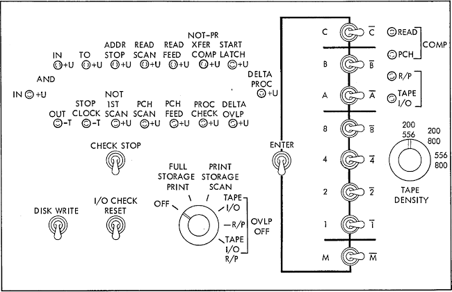
The auxiliary console has multiple sync points for connection to test equipment. The CHECK STOP switch enables stopping on error conditions. The DISK WRITE switch enables and disables disk writes for testing. The I/O CHECK switch is for CE use and resets an I/O fault. The auxiliary mode switch selects print mode and controls overlap functions. The bit switches and ENTER switch are used to enter a character into memory. (Note that 0 is stored as 8 2 C.) The STERLING dial selects the desired shillings/pence encoding. (This optional dial is not shown but is above the auxiliary mode switch.) The TAPE DENSITY switch is used for tape I/O.
Debugging with the console
The console provides several operations that are useful for debugging. Registers and memory can be viewed and modified. Memory can be dumped to the printer. The most common operations are described below; the Reference Manual (pages 109-118) describes the console thoroughly.
Viewing registers or memory
To view a STAR register, press the register's button and its contents will be displayed in STORAGE ADDRESS.
To view a storage location, set the mode switch to CHARACTER DISPLAY. Set the desired address on the dials. Press START. The character will be displayed in the B register.
Modifying registers or memory
To modify an address register, set the mode switch to ALTER. Set the address on the dials. Press the desired register button. Press START.
To modify a memory location, set the mode switch to ALTER. Set the address on the dials. Set the character using the bit switches on the auxiliary console. Toggle ENTER on the auxiliary console. Note: make sure the parity is correct (odd), or the 1401 will check-stop when it uses the value.
To fill all memory with a character, set the mode switch to STORAGE SCAN. Enter the bit pattern on the auxiliary console switches. While holding ENTER up, press and hold START. Then release ENTER. Memory will be written until START is released. (This doen't seem to be documented.)
Single-stepping
To step through instructions, set the mode switch to I/EX. Press START to read one instruction from storage, and press START again to execute the instruction.
To step through instructions one cycle at a time, set the mode switch to SINGLE CYCLE PROCESS and press START to complete one cycle.
Printing storage
To dump out 100 characters of storage to the printer, set the mode switch to STORAGE PRINT OUT. Enter the desired (thousands and hundreds) address on the dials. Press START.
To dump out all of storage to the printer, set the mode switch to STORAGE PRINT OUT. Set the auxiliary mode switch to FULL STORAGE PRINT. Press START.