Weird Parts
Tim's InCircuit Tester
This page is currently very preliminary - under development -
Goals of this web page
Tim Coslet was the person who fixed most of our (1401 Restoration) defective SMS cards. His primary aid is an in-circuit tester that he built from plans in the magazine ???. Unfortunately, Tim has returned to Montana :-((
The write up from the trouble shooters speeded his search for bad parts. Tim, using his in-circuit tester, could get a good idea of circuit dynamic characterists with out unsoldering the parts for individual testing - a good thing! (After a part is really suspect from the in-circuit test, it is removed for individual testing and replacement.) The source of the problem is usually:
- an open diode (often cracked glass due to corrosion along the iron lead to glass interface)
- a low beta transistor unable to adequately pull down a logic line
- an open inductor
- occasionally a somewhat shorted diode that causes excessive load on the drive element
Using the in-circuit tester is not as straight forward as individual component testing - being an acquired art - but does speed diagnosis and reduces damage to parts and SMS card traces. :-))
(There have been thoughts of making SMS card testers and test programs. But with about 120 SMS card types and
several circuits per card and several tests per circuit - this would be a non-trivial task.)
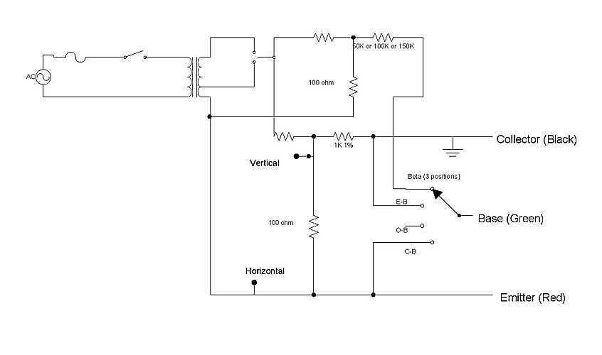
Tim's in-circuit tester | Notice on the left that the driving frequency is 60 Hertz, power line frequency - much lower than the service frequencies.
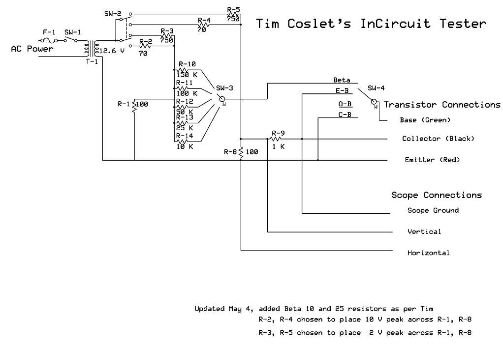
This is an expanded re-draw of the above - trying to get ready to make a duplicate of Tim's box.
| |
At the test frequencies and the resistances involved, the capacitors are practically open circuits and inductors are practically short circuits. These "reactive" components should not make phase changes (loops) in voltage vs. current curves at the much lower test frequency compared with the service frequencies.
Further details by Tim Coslet - Feb 23, 2006
|
The original design in the magazine used +-1V peak to avoid possible damage to semiconductors during in circuit test, but this is too small to turn on darlington transistor E-B junctions so I increased my design to +-2V. I also added a +-10V peak range to check reverse breakdown, low voltage zeners, and operate transistors at higher voltages. All the 1401 testing has been done on the +-10V range, as this seemed more "realistic" to me and I was having problems getting good Beta estimates on the +-2V range (due to an effect mentioned below almost all the transistors read very low Beta on that range, but more normal Beta on the +-10V range).
The scope was not set to 1V/div. I usually use 0.5V/div when using the +-2V range and 2V/div when using the +-10V range (so the curve fits the screen better). Unless I need to determine transistor type (Si/Ge) or breakdown voltages I'm more concerned with shape than exact voltage/current levels.
E-B is the Emitter-Base junction with the Collector shorted to Base.
These are standard test definitions given in datasheets that I wired into my switch, so that I would not have to keep swapping leads around. The Beta settings use an additional similar resistor network to inject current thorough the Emitter-Base junction while the main circuit is measuring the characteristics of the Emitter to Collector path (similar to the O-B measurement, but with the Base connected instead of open). The difference in the additional similar network is that the 1K resistor is replaced by a Beta*1K resistor (50K, 100K, and 150K in my box) and there are no scope connections to that circuit. To a first approximation, if the resistor selected exactly matches the Beta of the transistor then the curve drawn will be identical to the curve drawn in E-B mode, if the resistor selected is larger than the Beta of the transistor the curve drawn falls outward, if the resistor selected is smaller than the Beta of the transistor the curve drawn pulls inward. However this is never exact as the test circuit has no compensation for the E-B diode characteristics (a second approximation effect that changes between transistor types) and the curve sometimes begins falling outward then pulls inward. ... -- |
|
Here are some similar things probably derived from the same magazine article:
http://www.techlib.com/electronics/curvetrace.html
http://www.repairfaq.org/REPAIR/F_semitest.html#stict
|
return to main page