Schedule December 2007
return to main 1401 Restoration Page
go to Team Bios
Contents:
Wednesday December 5 - general
It appear the system has not been serviced since 1997.
While checking out the unit, we found a large wall mounted switch that appeared to allow the selection of power
to the room from the UPS system or PG&E.
Since the room no longer requires UPS, we don't need the constant fan noise from the UPS unit and we could use the space, Dennis threw the switch today and shut down the USP for good. I brought up the power converter, the 1401 and a couple of keypunches and everything seemed to work fine. There does not seem to be a connection from the USP and any other computers in the building. Dennis is going to look into how to get the UPS out of the room and possibly sell it.
--------------------------------------------------------------------------------
While in the 1401 room, I took down the information on the two Liebert System 3 air conditioners.
The model numbers are FH199A-AAM. The attached PDF file is the technical manual for the series including the FH199A.
This unit weighs 1845 pounds. ...
In another e-mail, John mentioned
I used to watch them wrap boards in Poughkeepsie. These machines had 2 wrap heads and 2 positioning pins all under control of servos. There was a reel of yellow wire about 3 feet in diameter and 18 inches wide feeding into the machine. It would strip the wire on both ends and the positioning pins would go down over the via pins bending the wire there and wrap heads would wrap the to and from pins. It was very fast and hard to really see what was going on. This machine wrapped one end of the wire in a clockwise direction and the other end was counter-clockwise. We had a manual unwrap tool in our tool bag that one end was for unwrapping clockwise and the other end for counter-clockwise. We could tell if a wire was put on at the factory as all our field tools wrapped clockwise.
They had a 1401 connected to a special built machine that looked like a pizza oven. The board was place in it with the pins up and a contact panel lowered to contact each spring loaded pin. The 1401 would put a voltage on a pin and scan all the others to see where it went. This would detect opens and shorts. It didn't take the 1401 long to scan every pin in the board. If any errors were found they were printed out on a B1 typewriter. There was a woman there that corrected any mistakes. If she made more than 3 corrections the board had to go through the pizza oven again.
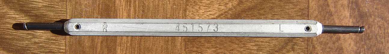
John's dual direction unwrap tool.
From Grant Saviers, Dec 1, 2007
Wednesday December 12 - general
Thursday December 13 - tape
We fixed the backspace problem that Allen and Ron reported. A NAND gate
in the Go reset circuit was dead. As a result, Go was staying up from
the beginning of the Backspace instruction, to the end of the Read
instruction. (In the Write-Backspace-Read sequence)
We also were able to transfer records (not just data bytes) from the
emulator to the 1401. The TAU seems to be happy with our timing and
control handshakes.
Next week we plan to bring up the echo data part of write record
operations. (We got the write data transfer to the emulator working last
week.)
Regards,
Wed December 19 - general
Regards,
--Peter R. Samson.
Judith sent this
report, in both OpenSource and WORD, this is from the OpenSource version.
So, Bob, the next time you're in, you will find a big oily can of oil
sitting behind the 513. It's in the 5 gallon can, so you will need a
funnel and ideally something smaller to pour it into. If I can make it,
I'll try and come in on Jan 2. just for the fun. I should be able to
make it there in the morning.
Judith, who now knows a lot more about oil than she did on Wednesday.
and still later
Thurs December 20 - tape
Wed December 05 - general,
Thurs December 06 - tape,
Sat December 08 - 2nd Sat.
Wed December 12 - general,
Thurs December 13 - tape
Wed December 19 - general,
Thurs December 20 - tape,
Responses from last Wednesday
Liebert e-mail from Stan Paddock
Dennis Cassar, Facilities Technician, and I talked about the alarm sounding on the UPS in the back of the 1401 restoration room.
For an 8.5 megabyte manual, click here - Stan says
"In this document it [our FH199A-AAM] is refered to as DH/VH199A on page 16 4th column."
From John Van Gardner, Nov 31, 2007
For full text of analysis, click here
There are 33 cards in the 01A4 gate that have red wires going to them. Cards F01 thru F24 and D05 thru D13.
None of these cards show up on the plug list for the machine. I'll bet someone installed a bootleged
STL feature on that machine and they only had a wire and card list and nothing to increase the power
to the gate. It would be interesting to power the machine on and measure the current from the -12 volt
20 amp supply in a static state and then power off and back all those cards out and power up and measure
the current again. I wonder how much current 33 cards draw.
Van Gardner
It was a lot easier and cheaper to let the Gardner-Denver put the wires in when the board was manufactured. This was a big help in reducing field installation time.
I don't know about the UPS status but the decommissioning and mothballing of the generator happened several years ago.
Grant
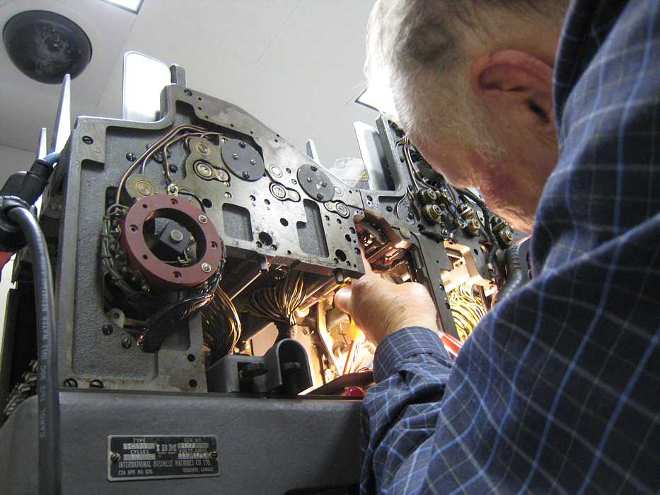
We were getting set up to measure -12 volt current in the 33 cards of added Selective Tape Print logic that John Van Gardner noted.
We were discussing measuring the current difference through the one milliohm wire that Ron Crane had measured when we
noted that a Space Invader (Stan Paddock) had taken over the computer. ;-))
A week ago there was an episode where column 92 of the 1403 failed to print for a while. The odd thing was that there was
no "Print Check" error. (IBM used the back EMF of the printer magnet to sense troubles. While Frank King was trouble shooting,
the printer started working properly again :-| Intermittents are the bane of any CE's life :-(( So today Frank started
full fledged investigation.
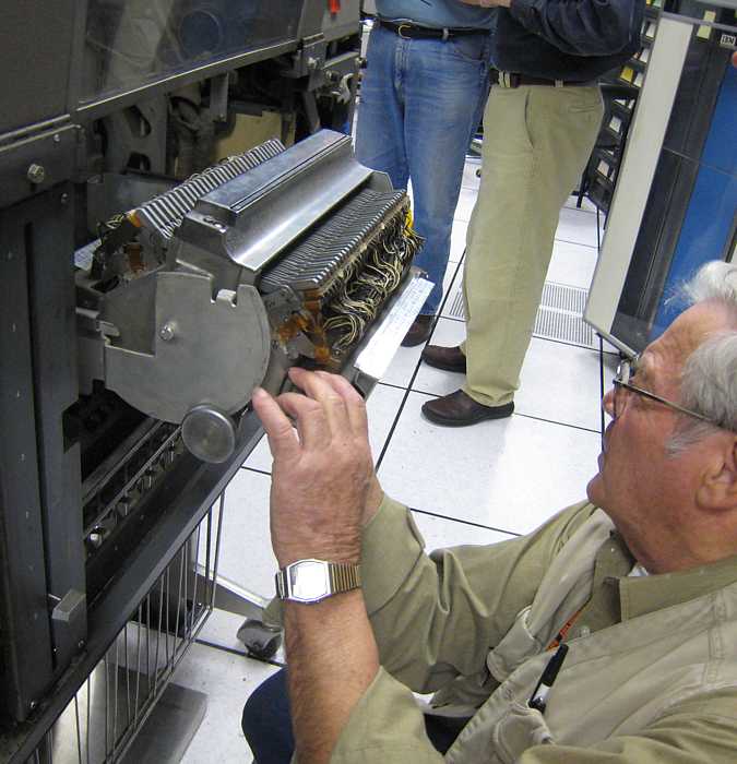
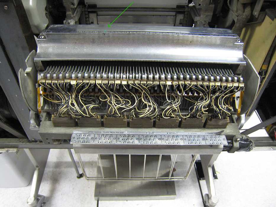
The green marked hammer is the guilty # 92
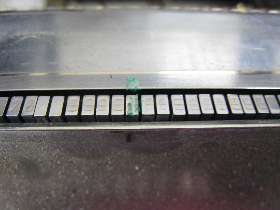
Part of 132 hammers, see green arrow.
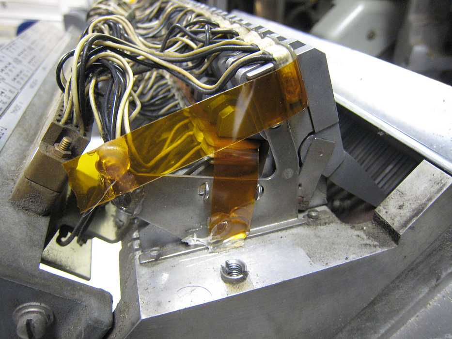
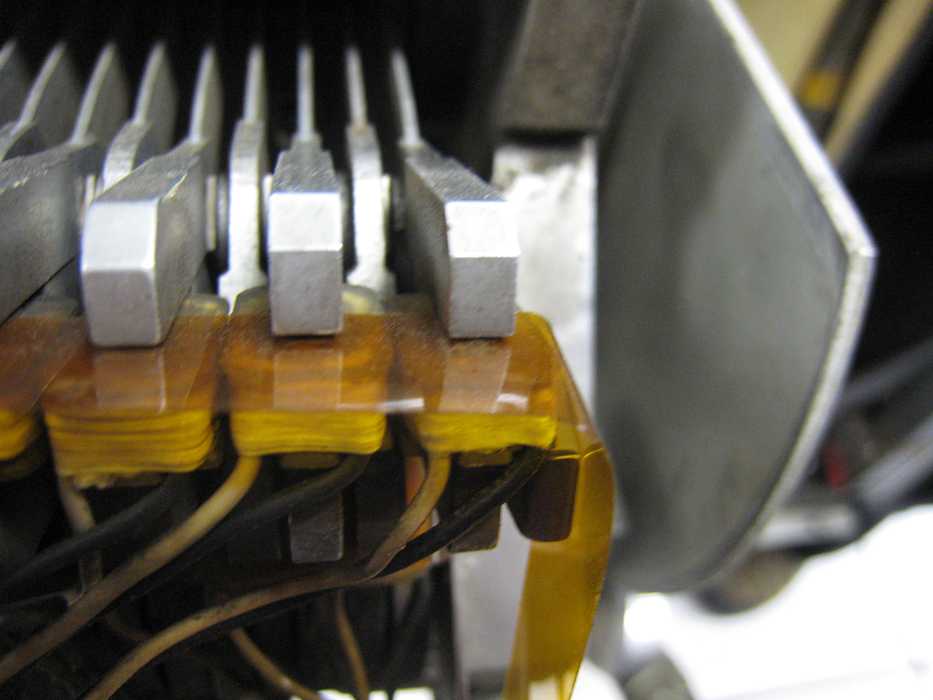
Frank checked for loose wires, wiggled the plugs, eyeballed the wiring, but no cause was identified :-((
An early thought was that the tape that provides about 0.005 inch magnetic gap between magnet and armature may
have failed in an odd way, but no!
In the meantime, Bob Erickson had isolated an operational fault in the 513. The machine refused to RunOut cards properly
if the input hopper had run out of cards. A switch in an almost in accessible place was failing. Removing the switch
for cleaning was verry difficult. Reinserting it was worse. You need a mirror to see what you are doing.
A mirror gives a backward view. Bob Erickson tried for 20 minutes - he said that if
we couldn't get the switch back in, he would have to take the 513 apart again to get better access. Ed tried for 5 minutes -
couldn't even get his hands all the way in there.
Ron Williams was then called. This is Ron struggling.
We are hoping Judith is coming in Saturday. Maybe she can do it?
And we had major excitement - It started innocently enough - trying to identify which circuits went where from the Power Distribution
Cabinet. With out getting into unfortunate details, about 4:00 the Vice President of Information Systems came in and asked if
we might have operated some switches which dropped power from various Computer History Museum servers, including the web site?
Well, yes we might have. Here is the resulting sign.
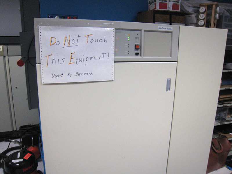
E-mails have been flying ever since !!
Thurs December 06 - tape,
TAU Debug Status 12/6/07 - Jeff S., Ron W., & Bob F
Today we connected the IBM 1401 Tape Channel Analyzer, with its PIC
processor installed, to the tape channel for the first time and
tried to run tape operations. After some start-up problems, we had
quite a bit of success.
Our goal for the day was to successfully emulate a Rewind operation (a
simple control signal only operation between the TAU and the Analyzer)
and to perform the part of a tape Write operation that moves data from
the 1401 memory to the Analyzer. Normally, the data is echoed back to
the TAU, but that code is still TDB.
The plan for next week is to attempt a tape Read operation from the
emulator. This operation will place Grant's Tape Channel Analyzer's
Analog Board through its paces.
Regards,
Bob
Saturday December 08 - 2nd Saturday,
Executive Summary - the glass is half full, we didn't break anything or anybody. :-))
Successes: Jim Somers brought in sandwiches, supplied afternoon cookies. :-))
The following in "GN" (good news), "BN" (bad news) format
GN - Stan Paddock installed the card station switch (Wednesday above) by setting up 3 chairs
in a row and laying on his back.
BN - Unfortunately something else was wrong and it had to be removed again. :-((
GN - Stan also worked on #1 026 keypunch BACKSPACE key.
BN - Unfortunately it still has the sign "Do not use the BACKSPACE key." :-((
GN - Bob Erickson and Judith Haemmerle gave the machine a "3000 card oil change".
BN - Unfortunately it was neither scheduled nor needed :-((
GN - Bob Feritich returned a call by Ron Williams about the location of the "Baker 9" schematics, now found.
BN - Unfortunately, that didn't help :-((
GN - Tim Coslet finally figured how to correctly test a "S" level card which was reported bad
from a 729 mod tape drive.
("S" level goes between -6 and -12, a third logic level pair in our 1401 equipment.)
BN - The card appears to function properly, something else must be bad. :-((
GN - the ordered PC USB 24 relay box arrived at Stan's house
BN - Stan Paddock did not bring to drive an 026 key punch. :-((
BN - Ed Thelen wasn't ready for it either. :-((
We should have been strolling in a park on this beautiful day
bob cat urine
From Bob Feretich
TAU Status - Thursday, Dec. 13 (Jeff S., Grant S., & me)
Bob
Just a reminder that the annual carol sing-along with the PDP-1 will
be on Dec. 19 (Wednesday) from 3:30 to 4:00 o'clock.
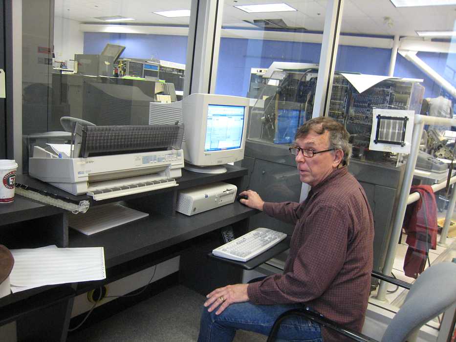
Stan Paddock completed his PC -> 026 keypunch circuits and started keypunching test data decks from the PC


Of the first 25 cards punched, 5 had defects, identical punches in adjacent columns, and/or missing punches.
He later sent this e-mail. "I got it up to 99.5% today. I think I have to break down and put a scope on it.
I expect to be in over the holidays."
This is Stan installing a PC in the entryway, available for tourists to see HTML presentations and other uses.
Later
We have Oil!
I called the industrial tech support for three major oil companies. The
best ones were Shell and Mobil. They actually recommended the same oil,
so I"m feeling fairly confident about it. Mobil gave me the name of the
local distributor for their oil, and they had just shipped out their
last 2 cans of it - it comes only in 5 gallon drums, which is a little
more than we need. So she gave me the name of the company that bought
it, and I called them, asking if we could have a cup of oil. The
parts/supplies person was really friendly, so I drove up to Oakland and
they have me what was left in a 5 gallon can. I'm not sure how much is
really in there, but I suspect we have enough oil to last well into the
next few decades, even if we do 3000-card oil changes. ;)
By now you have my
story of the oil adventure, and what we are going to try is Mobil's DTE
BB ISO 220 gear oil, which does not have detergent additives -
apparently that's one of the problems with what we have. It was donated
by A B & I Foundry in Oakland.
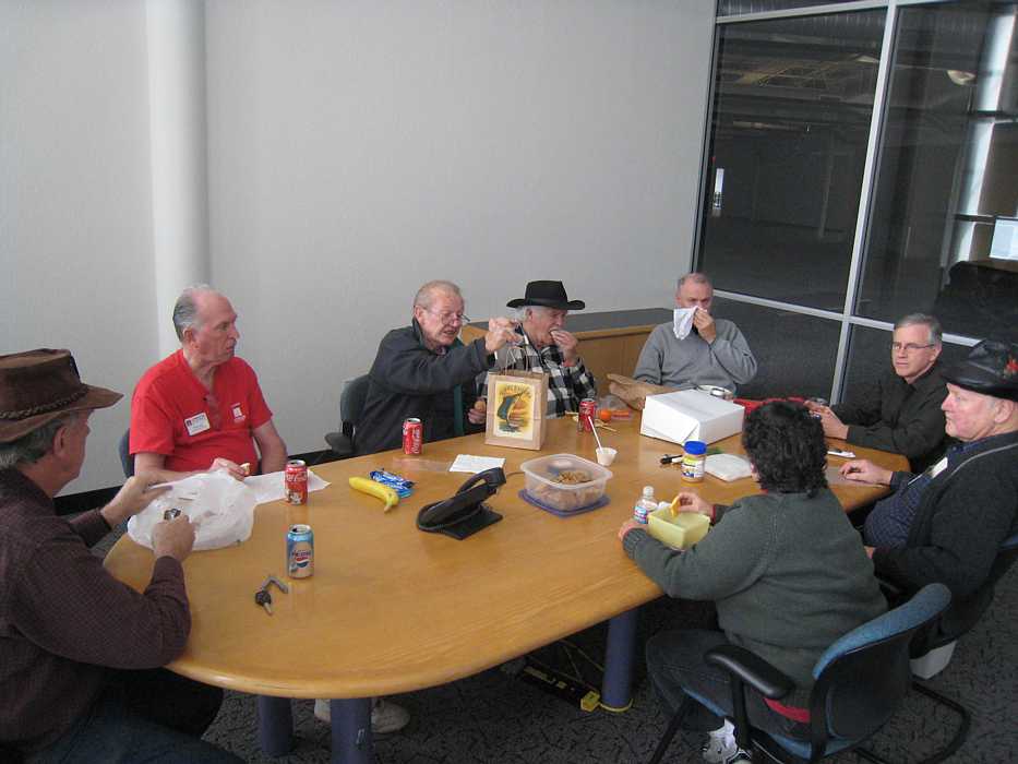
Here we are at lunch
1401 Tape System Debug Status - Thursday, Dec. 20, 2007 (Jeff S., James Dougherty, & me)
Regarding the problem reported by Allen about the beginnings of records not being read when a Write-Backspace-Read loop is run: Tape Emulator Progress:
- We examined the 1401 Tape Adapter Unit's (TAU's) Go, Backwards, & Read Cond. timings with respect to the data pulses. All of the timings matched specifications.
- We noticed that the problem did not occur when the program was I/Ex stepped.
- We noticed that the amplitude of some of the Read Bus signals were a bit low. Some around 6Vp-p instead of the 8Vp-p spec value. We increased the gain on all bits to 8Vp-p. This maxed out some of the adjustment pots.
- The above adjustment seemed to fix the problem. At least temporarily....
- We believe that the root problem is the prolays bounce and tape start/stop times. We know that the tape does not come up to speed fast enough. We know that the read data shows amplitude fluxuations during the first few characters of a record. We documented this problem on October 11th. (Sched2007October.html#11) I think that the next step is to machine new, stickier, capstan rollers. I believe that the 40 year old rubber on the current rollers has become too hard and slick.
Happy Holidays. Our team does not plan to come in next week.
- We were able to perform Tape Read operations to the Emulator and it returned the correct record data to 1401 memory. I reported this working last week, but since then I rewrote sections of the read data interrupt handler, and it was good to see that I didn't break it too badly.
- We were able to perform Tape Write operations to the Emulator. The correct data was buffered in the Emulator. The TAU was happy with the control handshakes and echoed data.
- However, we received intermittent Echo Pulse errors. This was due to two problems. First, the pulse being generated by the Emulator was too short. We increased the pulse width from 1 usec to 4 usec. The pulse width is being generated by firmware and 4 usec is too long of a pulse to conveniently generate. (The write pulse interrupt routine executes completely in about 1 usec. Adding 3 usec of delay would exceed its time budget.) I plan to examine adding hardware to the emulator to shape this pulse.
- Second, we noticed up to 25 usec of jitter on the leading edge of the Echo Pulse. We believe this is due to something executing at the interrupt priority level for an excessive period of time. Currently, we can't think of anything that would tie up the processor for that long (~200 instructions). This problem is critical since at 200 cpi, only 20 usec of jitter can be tolerated. (At 800 cpi, only 5 usecs) This is the #1 problem to be worked on for the next week.
Regards,
Bob FeretichFrom Allen Palmer - Friday
Bob It concerns me that the 'read bus' voltages were less that 8.8 pp/v. The spec's calls for 10v p/p with the amps turn up full. The fact that you could not get up to 8.8v with some worried me
Ron Crane and I set all read channels to the 8.8 pp/v. two weeks ago using a new tape as called out in the book. I have noticed that which reel of tape you use has a significant impact on these reading. We need to either get some new tapes, set the machine for these and then if we want to use those old tapes we will need to check the read output for each as we use them. Either that or there are more problems in the read circuitry
We will need to check what the p/p V off the read head is to see if we are getting a signal within spec.
We could have a problem with ''write'' quality. Will check that out again. There is always the possibility of a worn head. If that is the problem then the drive is ''shot'' since we have no spare heads and heads are not swappable from one model to another. Maybe Grant could look at it if it comes to that.
As to the capstan rollers, with Grant's help to make the new rollers, swapping them should not be a big job ( I heard that before, so why do I believe it this time).
The effect of just plain age on many of the parts is much more than I would have thought. Looks as though everything that is '' rubber'' ... drive belts, stop capstans, rolling capstans, hoses, harness wires, hi-speed rewind coupler , cog belts ... all of them are just plain ;shot'
Which brings to mind the question about the New York drives. The drive problems do not seem to be ''how longer ago was the machine turned off'' or storage conditions or usage but just plain age. Just age. I suspect that we will find many of the same problems with the NY drives. They are all from the same era.
Allen j Palmer
From Bob Feretich - Saturday
The physical symptom is that when a record is read from tape, sometimes the first few characters are not stored into 1401 memory. A 9 character record consisting of "ABCDEFGHI" may appear in memory as a 6 character record "DEFGHI". The number of characters dropped from the beginning of the record varies from read to read. To troubleshoot this problem we recorded a tape with one very very very long record (the entire tape was one record). All bits were on for each character. When characters of this record pass over the read head, a constant stream of Gaussian pulses are transmitted on the Read Bus cable to the TAU.
As Grant stated, the gain adjustments will probably not be a lasting fix. We need to do something to get the tape to accelerate faster.
- The tape is recorded as described above, rewound, and is ready for reading.
- Grant's sampling oscilloscope is set to record the startup of the tape. Channel 1 is the +Go signal (the scope is set to trigger on the rise of this signal). Channel 2 is one of the Read Bus signals (We normally use a signal from the middle of the read head (the 8 bit as numbered CBA8421).
- Using the TAU Control Panel, we start a Read Record operation. The scope captures the positive Go transition and the data bit for and about 5 milliseconds. Since there is a data bit recorded on the tape every 24 microseconds, we can see how amplitude of the Read Bus signal grows from zero to an 8Vp-p signal. Photos of this event are posted on the project web page at http://www.ed-thelen.org/1401Project/Sched2007October.html#11. The CE Manual pictures show that the signal must be at and maintain full amplitude in about 2.5 milliseconds after the positive Go transition. Our scope pictures shows our drive reaching full amplitude about 3.5 milliseconds after Go. We also occasionally saw the read amplitude drop off temporarily after reaching full amplitude. Our guess was that the temporary drop off was due to prolays bounce.
Regards,
Bob FeretichFrom Grant Saviers - Sunday
When I examined the capstans and did some measurements, I noted that there is a worn groove of about 0.002 - 0.003" on the diameter the width of the tape. I suggest that Allen brings two worn capstans to my shop and I will turn or grind them flat. Then try these refurbished ones and then run the tests to see if there is any difference in start times. If I remove 0.005" the speed change will be about -0.45% which should not affect reading or writing. If this fix doesn't work then I will order some neoprene to make new capstan surfaces.
Grant
Happy Holidays and see you all in the New Year!
Allen replied"Grant
"I will bring both the capstan motor/roller & the plastic roller on the prolay. We can check both.
"A happy holiday to you and Dorrit
"And to all on this message.
"See you next year.
"Allen j Palmer"
Go to January 2008
go to Team Bios