Schedule June 2006
return to main 1401 Restoration Page
go to Team Bios
go to July 2006
Contents:
Thursday June 01 - TAU Team
Wednesday June 07 - general,
Thursday June 08 - TAU Team,
Saturday June 10 - 2nd Saturday
Wednesday June 14 - general,
Thursday June 15 - TAU Team,
Wednesday June 21 - general,
Thursday June 22 - Tape Team.
Saturday June 24 - 4th Saturday
Wednesday June 28 - general,
Thursday June 29 - TAU Team
Thursday June 01 - TAU Team - report from Bob Feretich -
Tell me when you next plan to be at the CHM working and I will join you and we can layout a plan before we start to make individual adjustments. There is a step by step procedure for these measurements and adjustments.
I would rather continue to debug the Write operation and build confidence that the data that we are writing is correct. Then use tapes that we created to debug the Read operation.
I don't remember any markings on the tape reel. If there are no markings, then how can you tell? I would have thought that any modern tape would be backwards compatible.
Regards,
IBM documents mention four generations of 1/2" open reel tape
One way to determine older tapes is that they have the "3 hole" plastic flanges and often have plastic hubs. These are almost certainly 7 track and likely less than 800cpi. The open hole reels proved to be poor for several reasons: handling could damage the edge of the tape, dirt could get into the tape pack, and hubs split with extended use. IBM and the industry switched to metal hubs and solid flange reels to solve these problems.
As tape linear velocities increased, managing accumulated and tension induced static charge became more important, especially with single capstan drive technology. "Back coating" tapes with conductive layers was introduced, but I don't recall who was first. 3M had a product called "Black Watch" as the backcoating was black. These would be the 5th generation of 1/2" open reel tapes.
My belief, but I can't document it, is that the higher density oxide coating formulations were thinner and had better magnetic properties (higher coercivity and higher Bsat). It would be likely then that a 1600bpi tape written and readback on a 200/556/800 drive would have low read signal output. Clearly manufacturers marked tapes as certified for 800bpi or 1600 or 6250 and I believe optimized their oxide & binder system formulations to minimize errors and maximize durability and interchange. Backward compatibility, when it existed (obviously there was no 9 track reading of 7 track tapes), was read only on 6250 drives for 1600.
During my 1401 operating experience in 1966, we had many "3 hole reels" in a production library of 500 or so tapes. We found 800cpi operation to not have adequate reliability (with IBM branded tape) for a production accounting system. All tape operations were at 556cpi. Drives were completely cleaned at the beginning of every 8 hour shift as I noted in my previous email. IBM cleaner was used. We had some very nice 4"x4" non linting disposable cleaning pads, maybe made by IBM, that worked very well when saturated with IBM cleaner. Head, vacuum port, prolay rollers, capstans, idlers, and both vacuum columns were cleaned, until a clean pad showed no oxide/binder residue.
A 1962 IBM service document I browsed had notes forbidding carbon-tet as a cleaner, I assume for obvious health reasons, even though it was very effective. The formulation of the IBM cleaner is unknown to me, but based on its smell it definitely wasn't alcohol based. A guess would be xylene plus 1-1-1 trichlorethylene, a non-polar solvent. Either will dissolve some binder systems. If we have some IBM cleaner, let's send it to a lab with a gas chromatograph and get it analyzed, as we need an ongoing source of a suitable solvent. Isopropyl alcohol doesn't dissolve binder and contains lots of water so is no good on two counts. DEC found that absolute ethyl alcohol did a fair job but it is hygroscopic and federally taxed (this was after tri-chlor hazards were recognized and it was being phased out of electronics manufacturing).
Perhaps we can find some volunteers that worked in the tape making business - IBM, 3M, Certron, BASF, Memorex, Nashua, and others ran coating and slitting operations.
Regards,
Grant
GE 94.
The GE 94 replacement lamp has a GE product code of 25829.
The bulb type of this GE 94 bulb is type S8. The GE 94 replacement bulb
has a base type of BA15d (Double Contact Bayonet). This GE 94 lamp is a
13.3 watt bulb. The GE 94 lamp is a 12.8 volt bulb. The maximum overall
length of the GE 94 replacement lamp is 2.000 inches or 50.8
millimeters. The light center length of this GE 94 lamp is 1.120
inches or 28.4 millimeters. The GE 94 replacement lamp is often
referred to by the product code 25829. The manufacturer continuous use
average life rating for this GE 94 bulb is 700 hours. This bulb has a
candle power rating of 15. The filament type of this GE 94 bulb is C-6.
about $1.75 each
Grant
Wednesday June 07 - general,
Thursday June 08 - TAU Team
TAU & 729-V Debug Status: (Jeff S., [and Ron Williams] and I; Dave
A. joined us after noon)
Next steps:
Regards,
Bob Feretich
From Allen Palmer
If you remove any cards in either the read or the write circuits, be very sure that you return each card to the exact location it was removed from. The reason is that r/w delay settings. Since we do not have a know master skew tape … we have we think is one ….. the plan to chart the delay setting for each drive and then develop a plan for setting the individual lines. With the cards in their original positions we should find each one in alignment.
From Bob Feretich to Grant Saviers - 6/4/2006
Grant Saviers wrote:
You might check the read circuit level thresholding logic in the TAU prior to adjusting the drive read peamp gains. For a normal read, I think the detection circuits should be ok for signals below 4v p-p, but don't know if they will be ok at 2v. Considering all of the variables the detectors should work for a 3 or 4 to 1 signal range, maybe more. For read after write the thresholds are set higher, so it could be the logic is stuck at this setting. There are also some threshold setting jumpers on the TAU read detection cards, but I would assume they should be left alone for now.
There are separate circuits in the TAU for low and high detection thresholds. The incoming Read Bits are fed to both circuits. For "read after write" (write echo) the Tau make sure that the "high threshold" circuit interprets correct data. As of last Thursday, neither circuit was detecting data's weak signals. The tape drive's read preamp gain is easily adjusted. We can reduce the gain later to test TAU receiver detection thresholds.
I also think it will be easier to get READ to work first rather than the extra complexities of read after write. Try some of the tapes in inventory to see how they work.
Actually working with the "write after read" data is easier than working with read. We can dynamically alter the bit patterns and density from the CE console switches. We also know that the TAU seems to be doing the right things during Writes. (We also know that Read turns on lots of errors in the TAU.)
The contents of the tape library are a mystery. We don't know the data to expect on the tape or the quality of the recording. I don't even know whether a given tape is recorded in 7-track or 9-track mode. I would also want to perform a lot more testing before we place one of the important tapes on the drive. I am not confident that it won't be damaged. Using tapes from the library would introduce another big and unnecessary variable into the TAU debug effort.
The 729's I used were cleaning sensitive. We cleaned pinch rollers, capstans, head, head cleaner and knife, and the both vacuum columns every eight hours.
You or Alan should train us on these maintenance procedures. We already have at least eight hours of operation on the heads and rollers.
Don't mix up the read pre-amp cards in the drive as they contain both the gain adjustment and the tapped delay line to deskew the read data.
All cards that we remove are being marked with their initial locations, and so far have been returned to these locations. Even cards borrowed from other tape drives have been returned to those drives after the original ones have been repaired.
Before setting the write current, make sure you have a NRZ tape for 800cpi as later tapes had higher coercivity and will not be adequately magnetized by the write head. A TEK current probe should be ok to measure actual current or a sense resistor voltage if there is one in the write amp (I don't remember the circuits and am in Cleveland).
There is a 100 Ohm resistor in series with the write head. The CE manual instructs us to measure the voltage across this resistor.
Bob
From Grant Saviers to Bob Feretich, Allen Palmer, et.al. - 6/6/2006
I did some googling and document scanning to find specs on IBM 1/2" magtapes but had no luck. As I recall, IBM did keep the technical details fairly hidden to make duplicating their products more difficult. The tape makers behaved likewise.
It is unlikely that acetate base tapes have survived. Early IBM tapes were made by 3M, however the prolays were too tough on their binder systems and IBM started making their own tapes in the 2nd/3rd generation.
From Grant Saviers to Bob Feretich, Allen Palmer, et.al. - 6/9/2006
here are the specs, it is a 12v bulb
The GE 94 replacement lamp has a Clear finish.
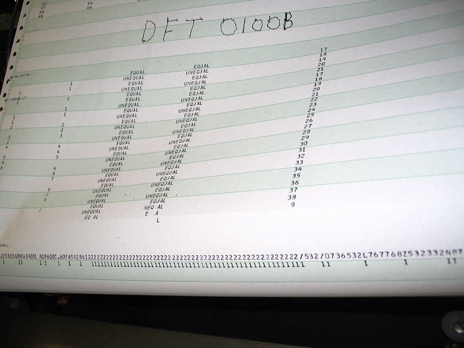
Ron Williams ran test 0100B in from the card reader. This test checks some of the condition codes,
using card input test conditions, and depending upon sense switch settings, prints out the results.
Here is a movie of the pocket selection. (7 megabytes)
Ron Williams also inserted test programs to read cards and send to selectable pockets in the 1402.
And here is a movie of reading a stack of cards. (4 megabytes)
After some reconsideration, Ron Williams proposed that we make the images available on our local laptop
that Grant gave us - and if there is a missing page, or an illegible page in the ALDs from Germany,
that page can be immediately looked up on the laptop and later printed.
We are forming a list of missing or illegible German pages to copy from
the CDROM to printer to insert into the German ALDs
from Bob Feretich
|
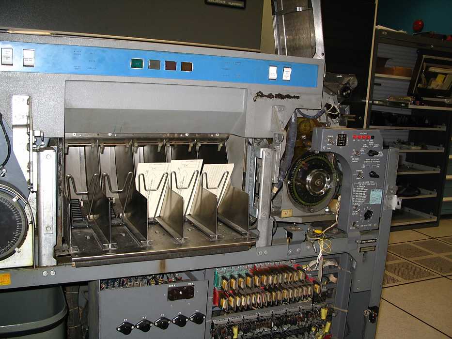
TAU/Drive Debug Status (Allen P., Grant S., Jeff S., Me, and Ron C.
(afternoon)
We started the debug session by cleaning the drive's head and vacuum columns. Since we move tape most of the day, this will become a ritual. CP16 (10A) popped several times early in the debug session. We placed a Ampmeter in the circuit and measured 6.3A, but we also measured a 2V drop across the meter and the test leads were very warm. Since the circuit supplies -7.5V, we expect that the real current is much higher. Based upon the filter capacitance and ripple, Grant calculated that current was at 10.5A. Grant will make heavier duty test leads for our next debug session. CP16 stopped popping after the drive warmed up. The "Write Current Adjustment" in the CE Maintenance Manual did not match the circuitry in the Model V drive. Our drive does not have a "Write Current Adjustment", instead it has a "Write Balance Adjustment". This control can set write current in one half of the write head circuit. We adjusted the balance for each bit so that the voltage drop across the pot matched the voltage drop across the fixed 100 Ohm resistor in the other half of the circuit. The voltage drops were set to 4.6V +/- 0.1V. We then adjusted Read pre-amp gain to achieve interface signal levels of 8Vp-p for each bit. Several adjustment pots had to be set to full maximum to achieve this level. We noticed that upward pulses were clipped at GND. Removing the Tape Analyzer's Analog Board from the bus fixed this problem. Grant will redesign the circuit to operate above ground. We now receive good data signals at the hi and lo clip amps. We plan to work both Wed. (CP16 debug, we can work offline) and Thurs. (continued TAU debug) this week.
Regards,
|
from Grant Saviers
|
I checked my schematic and it should work ok.
The cause of the problem, barring a component failure, is that the analyzer is in a "selected" state and this enables the analog read signal emitter follower bus drivers. They are base biased to close to ground and clipping the 729 read signal at ground as a result. If deselecting the analyzer doesn't solve the problem, we need to develop correct documentation for the 729 so this problem can be further investigated. Grant |
Saturday June 10 - 2nd Saturday
- Present were Ron Williams and Tim Coslet. Ed Thelen punched in at 10 , disappeared, and punched out at 3.
- Ron and Tim were having trouble with the "B" bit in the address range 8,000 to 15,999, and the 4 bit in the range of 12,000 to 15,999.
- And they were having trouble in that the machine did not match the ALDs and neither matched the plugging diagram :-((- Tim noted that a suspect card did not match the schematic :-((
The card had two large power transistors, and the schematic showed one. On the card, the two large power transistors were in parallel in the place of the one on the schematic - and there were some wiring differences.- I have been authorized to announce a
10 K RACE.Each machine races to count from one to ten thousand. Like add one to the accumulating sum until the value of 10,000 is reached.
In today's matchup, a 1401 and a Hp 15C handheld computer were entered.
This is Ron's program, you may disassemble it if you wish. (Much of the program is setting word marks.) 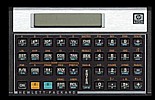
Tim did not release his script for the Hp 15C - patent pending - claiming it is his intellectual property and a trade secret. His attorneys, Screwum & Nukem, will vigorously defend his profit possibilities in court. ;-)) Ron and Tim revealed the results to me, but I will force you to click here to get the results from me :-))

Wednesday June 14 - general
- Present were: Ron Williams, Bob Erickson, Allen Palmer, Grant Saviers, Jeff Stutzman, Bob Feretich, Ed Thelen.
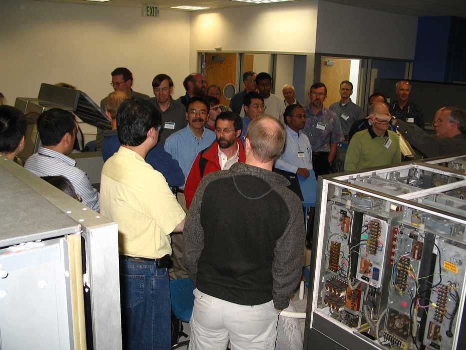
- We had lots of visitors:
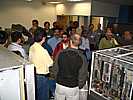
A group from IBM's Almadin Research was meeting at CHM, and many came to see "our" IBM 1401 ;-)) 
Tore Sinding Bekkedal, from Norway, had attended some hacker's conference in Mexico, and is now volunteering at CHM for a few weeks. I think he is crashing at Dag's place. This young man is extremely knowledgeable about antique and modern computers. He is very well read and has a retentive memory. He asked to borrow the IBM 1401 Reference Manual, and key punched a program to read and print cards. I was very relieved when it did not work the first time ;-)) - Ron Williams is continuing struggle with two memory planes in memory above 3,999. The cards and logic seem to check out. Next time we will look at currents and voltages in the X and Y drive windings, inhibit windings, and sense windings.
- Bob Erickson has decided to reduce the width of the compare in the 077 Collator, to avoid completely striping the Visual Storage unit of good compare magnets.
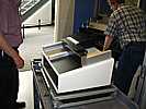
Grant Saviers brought in an e-bay "chad counter" (card reader to the rest of us) from Texas. This is a project tool, not a CHM artifact! We will have to contact Brian He said that the shipping was much more than the $45 purchase price :-)) From Bob Feretich - "TAU/drive debug status: (Allen, Grant, Jeff, and me)" - pictures and comments added by Ed Thelen
Today we tried to troubleshoot the CP16 circuit breaker problem. Allen noticed that a v-belt in the drive was cutting into a cable. Further debug discovered that the belt problem was due to a mis-positioned pulley. Unfortunately, the pulley position is frozen due to a stripped set screw. We needed to remove a motor from the 729 to drill out the screw.

CP16 popped several times. Now it will no longer reset. We need to locate a replacement circuit breaker. We need obtain a replacement breaker before the 729 can be effectively used to further TAU debug.
Tomorrow's (Thursday's) TAU/729 debug session is canceled.
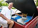
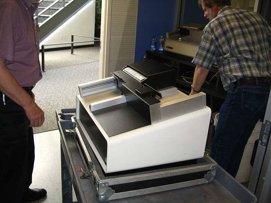
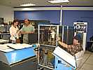
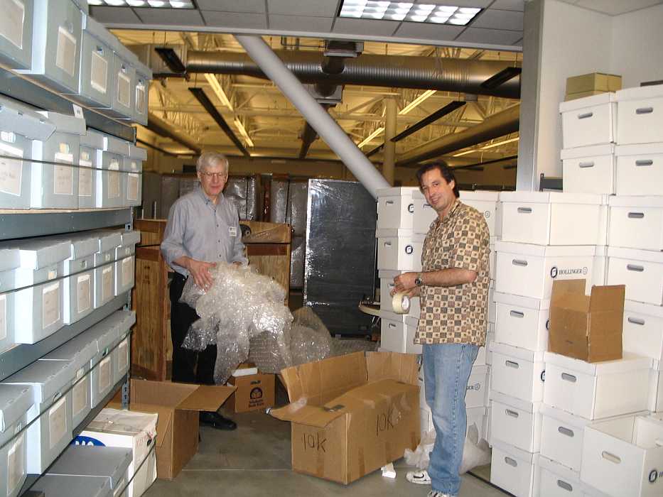
This is Allen Palmer (professional model ;-)) loading 4 boxes and clutches and motors for refurbishing at Grant's "Mountainside Machine Shop" ;-)). Next week we are planning to meet Wednesday and Thursday at Grant's shop. The focus will be to refurbish tape drive components.
Regards,
Bob Feretich


Thursday June 15 - TAU Team - meeting canceled as per Bob Feretich
Allen,
After reading what Grant wrote about tape in the 6/6/2006 daily report I decided to look through some of my sources and see if I could add to it.
1. Acetate base
2. Mylar base
3. Heavy duty
4. Series 500
We started out with all Acetate on the 704 and 705 at Lockheed until the Mylar came out. Occasionally an Acetate tape from the library would get put on one of the 729 Model 3 drives on the 705 Model III and it would just snap it. It could not stand the prolay action at 112.5" per second.
I found the following on page 211 of IBM's Early Computers:
"In 1956, Mylar (du Pont trademark) was substituted for the original cellulose acetate base, to provide greater strength and dimensional stability. Improved binders were introduced, in 1959 and subsequently, to provide the greater durability of magnetic coating required as the speed and acceleration of tape increased with higher-performance new tape units".
I thought the new binder was when they started calling the tape "Heavy Duty" but was not sure until I found the following in the 729 Customer Engineering Instruction-Reference manual form 223-6988 on page 5:
Mylar and H-D Tape
Width: 0.498 inch
Total thickness: .0019 inch
Ferromagnetic material and binder: .00045
Tensile strength (minimum): 12 pounds
The main physical difference between Mylar* and H-D tape is the binder used to secure the ferromagnetic coating to the plastic base material. H-D tape has better wear characteristics and gives longer service than regular Mylar tape. H-D tape is gray-black; regular Mylar tape is brown.
I tried to find something about the Series/500 tape but all I found was it's announcement in 1967 under Products & Services on page 29 at the IBM Archives site at:
http://www-03.ibm.com/ibm/history/documents/pdf/1885-1969.pdf
I did a search on eBay for "Black Watch Tape" and got quite a few hits. Some were made by 3M and some by Imation.
The 729 when if first came out it had two black 1/4x20 threaded knobs to squeeze a rubber ring on the hub to hold the reels. The picture in the front of the 729 manual shows these two black knobs. I have one and am attaching a couple of photos. The small female operators had trouble tightening the hub enough to keep the reels on and the large men had no trouble at all stripping the threads. IBM came out with a field change and replaced the black knobs with the knuckle latch like you have on your drives. This was an improvement for the operators but it started breaking a lots more reel hubs. On the back side where the groove for the file protect ring was only had about a 1/16'' of plastic left. About a third of this would break out and the reel would wobble and damage the edge of the tape. The aluminum hub solved that problem.
Allen, Did the 729s still have the black knobs when you started working on the line? I don't remember when it was changed but I installed a lot of them.
On page 23 of the 729 manual on the right column under CLEANING it says "Do not use Vythene IBM Cleaning Fluid P/N 450608. I have never heard the word Vythene before but the part number is the small gold can cleaner.
Van Gardner
Wednesday June 21 - general
Group at CHM, Group at Grant's worked parts for the remaining four 729 tape drives
Group at CHM
HOT FLASH
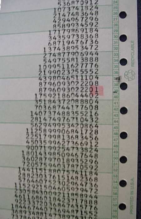
- Seemingly a real live computer bug, now hanging outside of Allison Akbay's office. The program adds the last printed line by its self and prints that. But our 1401 seems to have hiccuped?
This was printed while the machine had the instruction overlap problem, is this a result of that problem???- Ron Williams' report
- Present were Ron Williams, Bob Erickson, Don Cull. As they were leaving Ron Crane came in to work on 729 circuit breaker problem for a few hours.
- Ron Williams and Bob Erickson continued having problems with upper memory as mentioned previously.
- Don Cull identified that the 1402 punch problem is due to very mistimed 1402 timing contacts (called "CBs - Circuit Breakers by IBM). Some of the CBs don't even open. This may have occurred when a belt in the 1402 punch area broke and was replaced. The unit does not work at all and needs two people to retime it
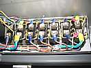
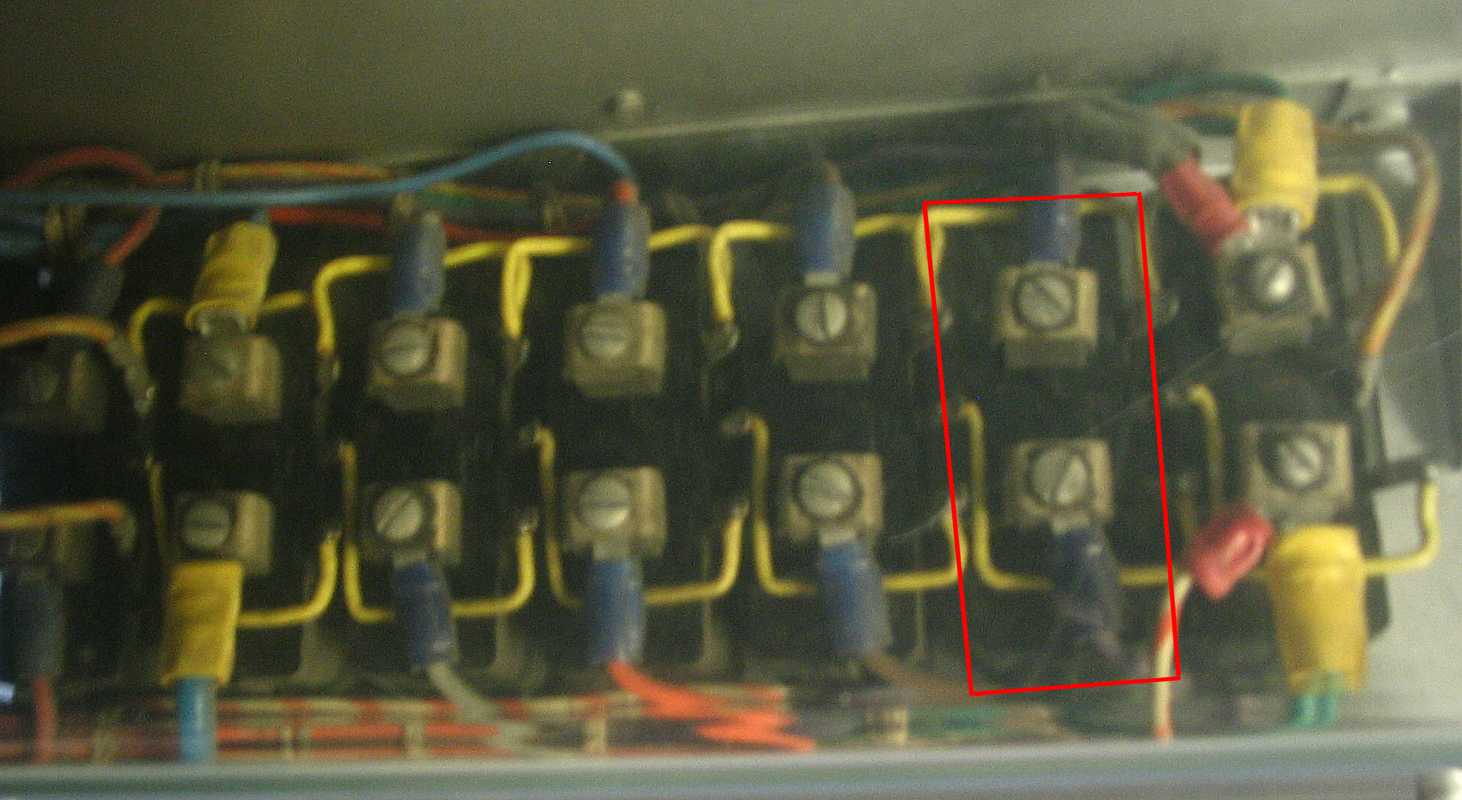
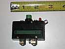
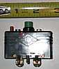
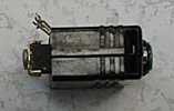
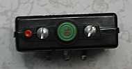
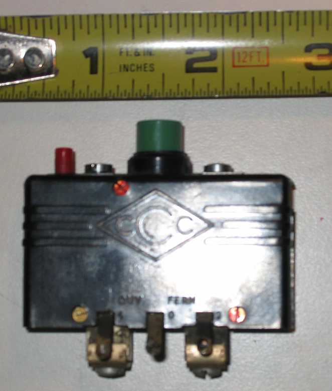
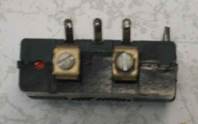
Ron Crane worked on the defective 10 amp Circuit Breaker (somewhat like used in your house wiring). In the past two weeks, this had been tripping erratically in our only working 729 and finally disabled it. :-(( I think Allen said the bad circuit breaker is the third from the right. - Ron Crane's report
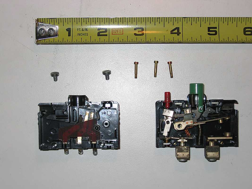
- Ron removed the defective -adjustable- circuit breaker from of the circuit,
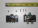
and disassembled it.- It is a thermal type, opening when the current warms it up over the trip level. No magnetic parts.
- He found that the reporting contacts (connected to the yellow wires) had rather high resistance, and the main contacts were quite blackened.
- He cleaned the main contacts, and reporting contacts, and noted design features that permitted the unit to work well over a wide range of temperatures.
- To get a test current, he went home for a 20 amp 4 volt transformer, then connected the primary side to a lab VARIAC and the secondary through a current meter and the circuit breaker.
- After adjustment, he ran 11 amps through the circuit breaker for 10 minites with out tripping it.
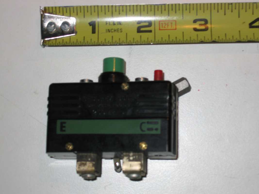
- He then ran 20 amps through it and it opened in 15 seconds. (An examination of catalogs indicated that the usual opening time at double current for thermal circuit breakers ranges from 6 to 30 seconds, so 15 seconds seems reasonable.
- Ron also noted that these circuit breaker run warm at rated current. The unit is very uncomfortable to the touch. Calculating from voltage drop and current, at rated current the circuit breaker disapated 2 watts. The breaker is a block about 0.8" wide, 2.2" long, 1.2 " high. The seven circuit breakers in this housing have about 3/16" separation and can be expected to run warm.

Thursday June 22 - Tape Team
Group at Grant's shop (on Mt. Hamilton Road) worked parts for the remaining four 729 tape drives
- Present were Allen Palmer, Grant Saviers, Bob Feretich, Jeff Stutzman, Ed Thelen - these guys start early - like 9:00 - - - I didn't :-((
- The goal was completing the refurbishing of the 24 clutch assemblies for the remaining four 729 tape drives.
- The 24 clutches are now completely disassembled, cleaned, sand blasted, de-sanded. New felt washers punched out using the special dies that Grant made. All that remains is:
- placing the correct measured amout of new magnetic powder in the 24 magnetic chambers
- reassembling the clutches with the new felt washers
Hmmm - does the magnetic powder leak out if the shaft isn't there to keep it in??- replacing the 24 clutches on the correct places of the the 8 shafts -
oh yes - one of the shafts is bent - what to do ??- We wound down about 3:00 - We had taken a one hour lunch and talked about amateur rockets.
Saturday June 24 - 4th Saturday
- Present were Ron Williams and Tim Coslet
- Good news and bad news
- Good News:
Lots of interesting visitors, Ed Thelen brought a fun group of komputer krazys (Forth Interest Group) through for a special visit after a "lecture" on restoring the IBM 1401 system. The The Sixteenth Annual Oughtred Society Slide Rule Collectors' Meeting also had a museum meeting room - and visited the 1401.)
(Actually the Forth group considered crashing the Oughtred society meeting, but cooler heads prevailed and a joint social was arranged for later. ;-)- Bad News:
After the regular and special visitors left, the ADD function in the 1401 failed. It failed so badly that a hand test program can't loop. Ron can't loop on and scope the failure. Ron Williams went home to see if beer tastes better than sick computers.
Wednesday June 28 - General -
- Present were Ron Williams, Don Cull, Robert Garner, Jeff Stutzman, Ron Crane, Ed Thelen
Allen Palmer, Bob Feretich and Grant Saviers were at Grant's shop re-assembling the 24 newly cleaned 729 reel clutches.- Kristin Abkemeier came from San Francisco to take notes on why people restore old computers. She wishes to make and sell an article to say a large national museum magazine. Robert introduced Kristin to the 1401 system - then spent some time talking with CHM administration
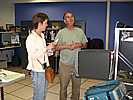
Kristin talking with Don Cull :-))

Ron Crane and Jeff Stutzman packed up all the 729 reel drive motors to take to Grant's shop to replace the bearings. They worked up there in the afternoon. - Various people have donated 1401 operator panel plastic plates to the project. Robert Garner and Dag Spicer of the CHM selected the nicest to replace the "panel" on the Visible Storage 1401. (Some years ago, someone had attempted to bring some apparent life the that 1401 by making a pseudo-panel with yellow LEDs and a complicated circuit to blink those LEDs.) Ron Williams removed the pseudo-panel and replace it with an authentic (and much better looking) panel :-))
- Ed used GoofOff to remove gunk from a 1' x 2' piece of aluminum that Grant had saved from the trash. Then marked off locations for fixed resistors to load test the 729 power supplies. Grant had supplied hand fulls of 5.1 ohm 20 watt and 21.1 ohm 30 watt resistors. The above aluminum plate will be the heat sink. The original idea was to use lots of switches to make general purpose loads - but that just doesn't seem practical. To test the 7.5 volts at 20 amps, we would have to generate a 0.375 ohm load capapable of sinking 140 watts. This would involve switching to parallel 13 of the 5.1 ohm resistors - not too easy to think about - We plan to drill and tap for 440 screws next week - hope to find and bring the thermal grease.
- The PDP-1 heat sinks got returned from Grant's workshop to the PDP-1 CHM mail drop.
- Grant lent two high current clip on probes to help with 729 power supply full load testing. One is Hall Effect for DC amps. They make life easier and more fun :-))
- Ron Williams found that the ADD instruction now works again - but the printer logic failed just after a demo.
- Last week, Ron Crane disassembled, cleaned, adjusted a troublesome 10 amp 729 circuit breaker. Now trips at 11 amps in 30 seconds and 20 amps in 15 seconds. :-)) He used a husky 4 volt transformer and VARIAC to get the testing currents


Wednesday, June 28th (Grant S., Allen P., Jeff S., and me)
We focused on re-assembling tape drive clutches. Got about half of them done. Also discovered that we (Grant) need to make a second die to cut out a different sized felt washer. Grant worked on the die design. Now that the clutch components are clean and we are trying to re-assemble them, we are noticing a few subtle differences between them. Despite our procedure to keep each set of components tagged with the unit and location it came from, we have managed to mix up a few sets. We think that we now understand the differences and how to re-assemble them. (Wish us luck.)
Thursday, June 29th (Grant S., Jeff S., Ron C. (afternoon), and me)
Since Allen was not present, we worked on refurbishing motors instead of clutches. We refurbished two drive motors. We had nine drive motors at the shop. One of these had been previously refurbished. One motor was not present (must still be on the second 729-V in the CHM lab). Jeff transported the motor set (two reel drive motors and the high speed rewind motor) for the first 729-V back to the CHM. That 729 should be ready to be reassembled and put back into service. (Hopefully, someone can do this next week.)
We have removed and cleaned all of the drive motor pulleys. Some needed to be drilled. Grant has ordered replacement set screws. We have seven motors yet to refurbish but only four sets of replacement bearings. Hopefully, four motors will have good bearings. So far, we have replaced the bearings on every motor that we worked on. Worst case, we order more bearings.
We arranged the clutches by drive and shaft. Jeff took pictures to document differences in clutch assemblies. We plan to submit the pictures along with our notation of differences to the project record.
Regards,
Bob [Feretich]