Return to 513 Summary Punch
Rwturn to 1402 Card Reader/Punch
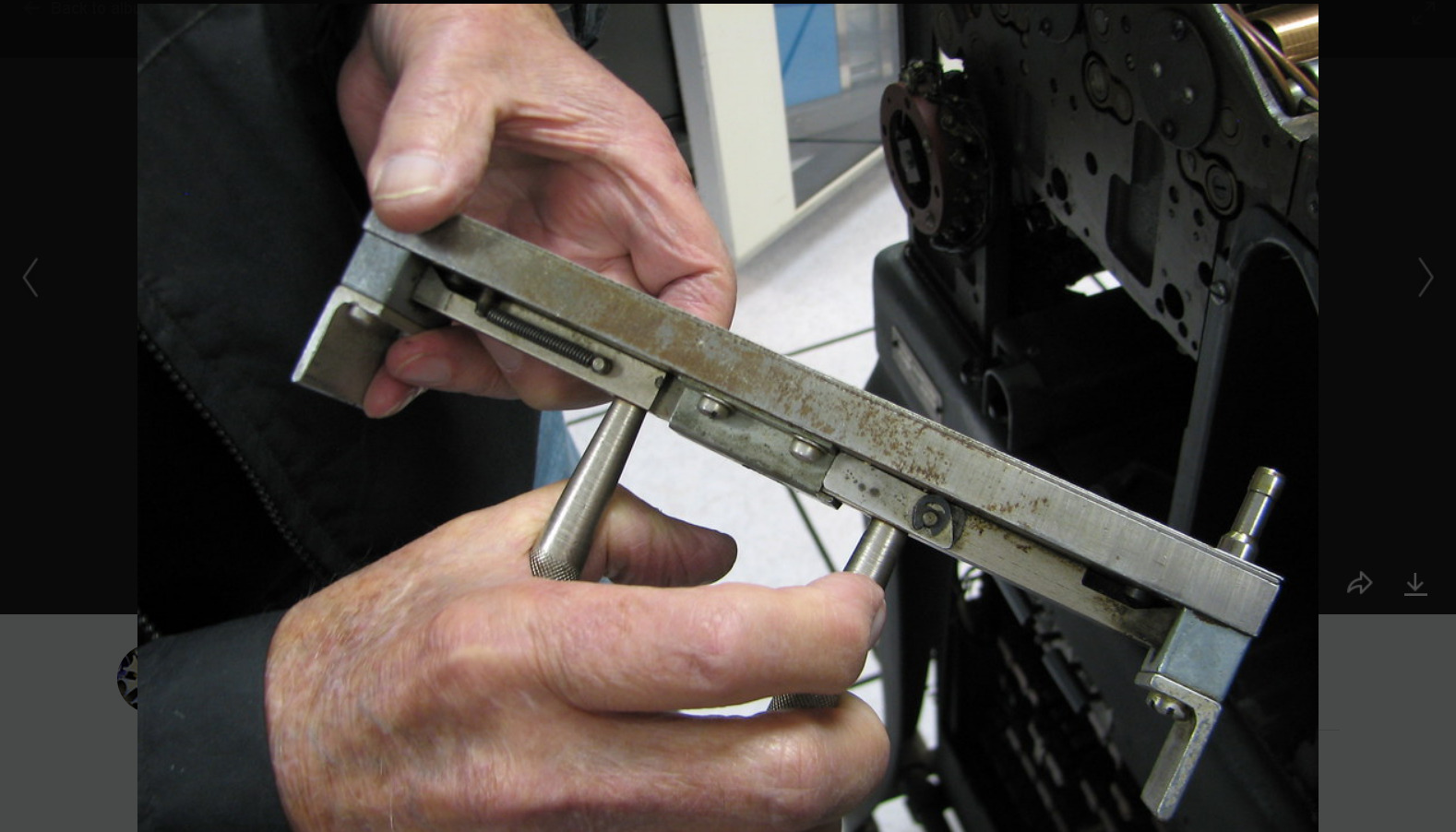
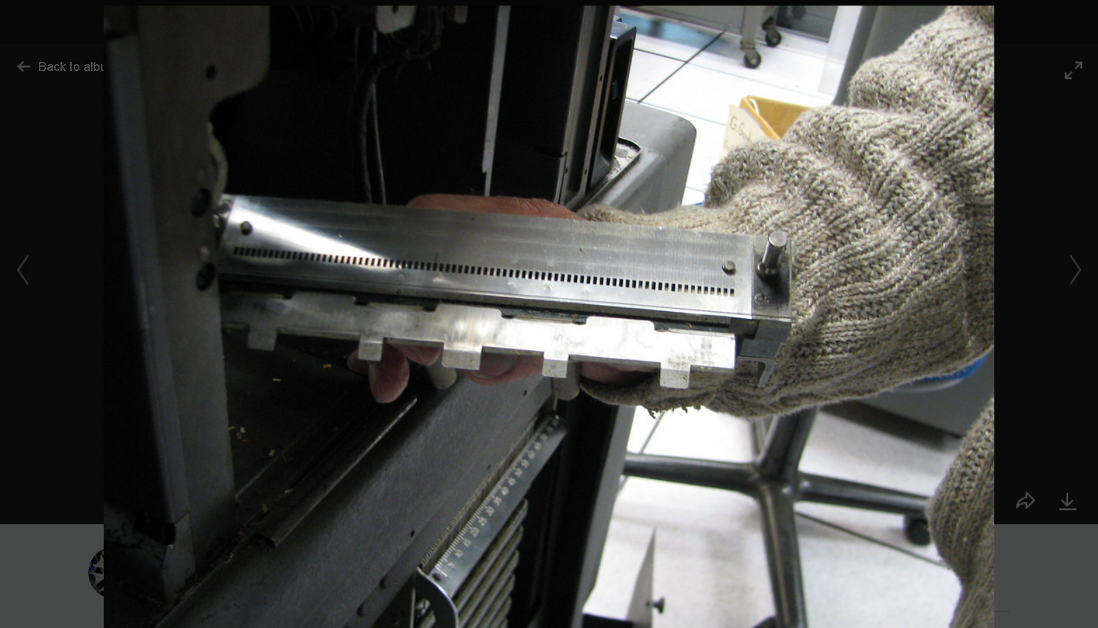
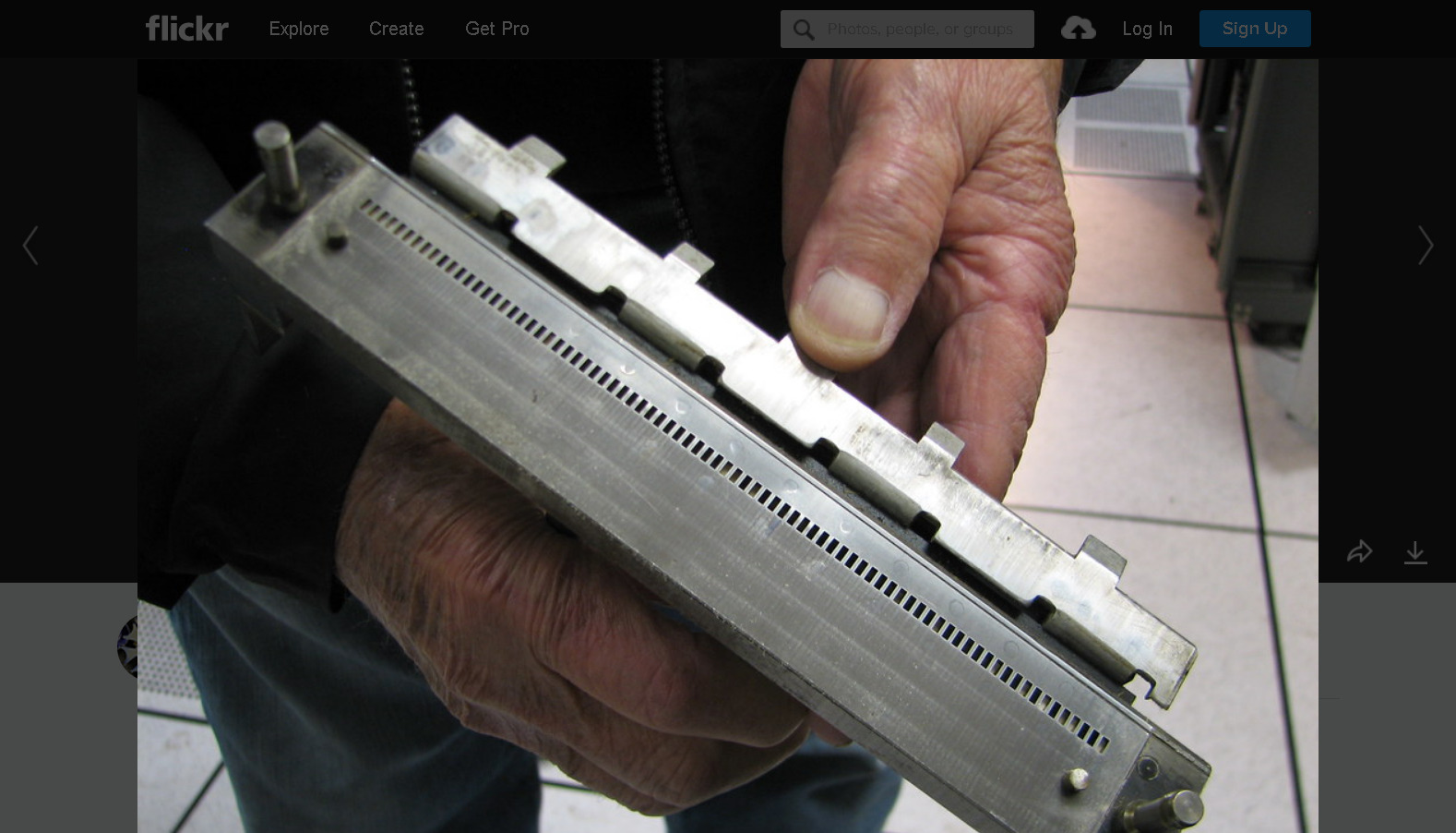
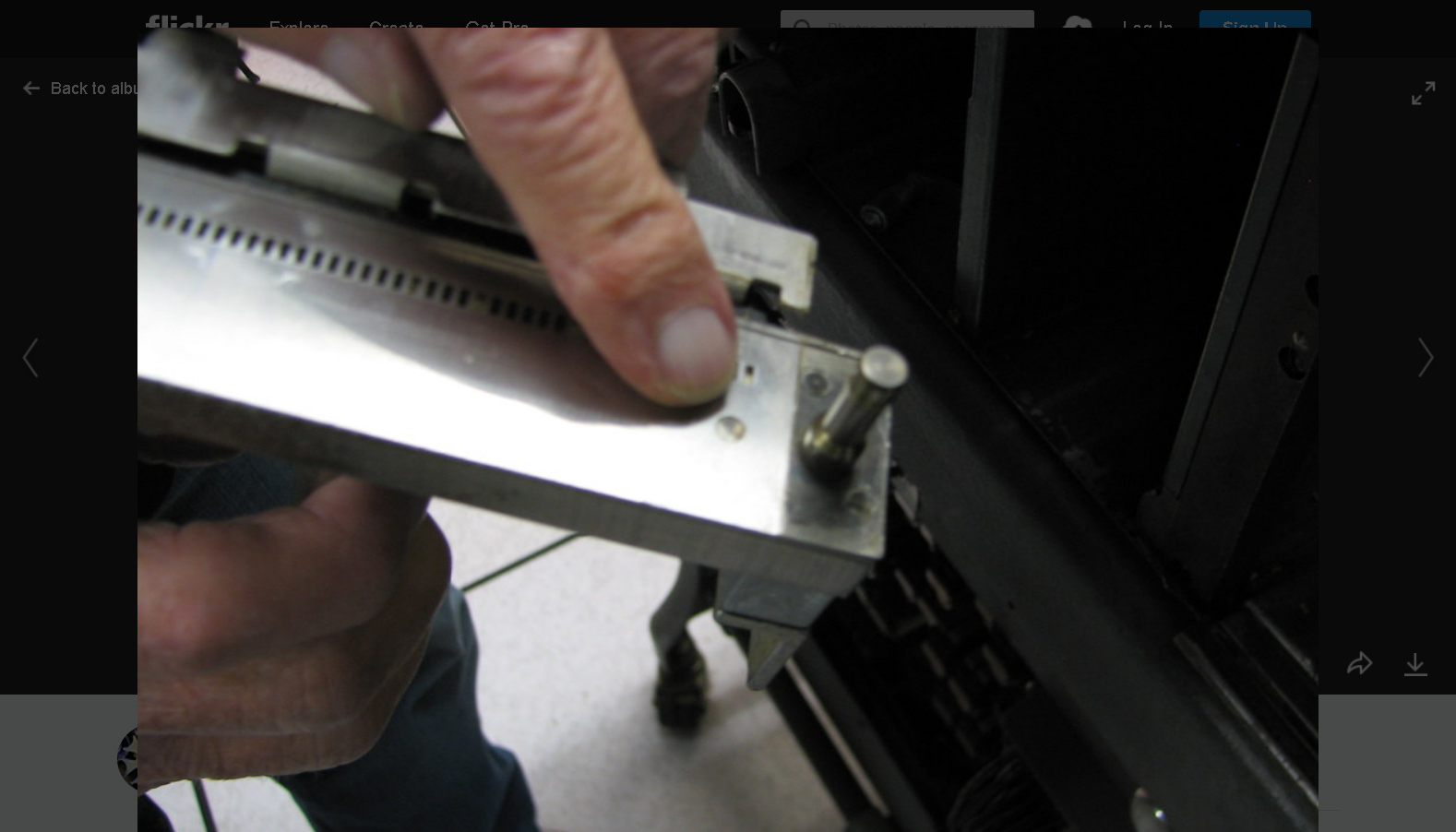
A Lubrication Guide for IBM High Speed Card Punches
IBM 513 Maintenance
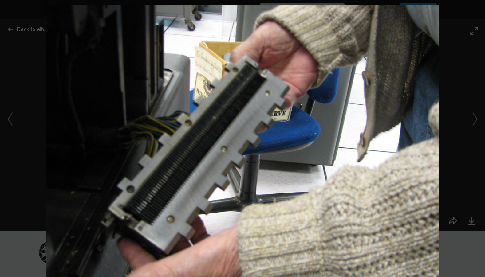
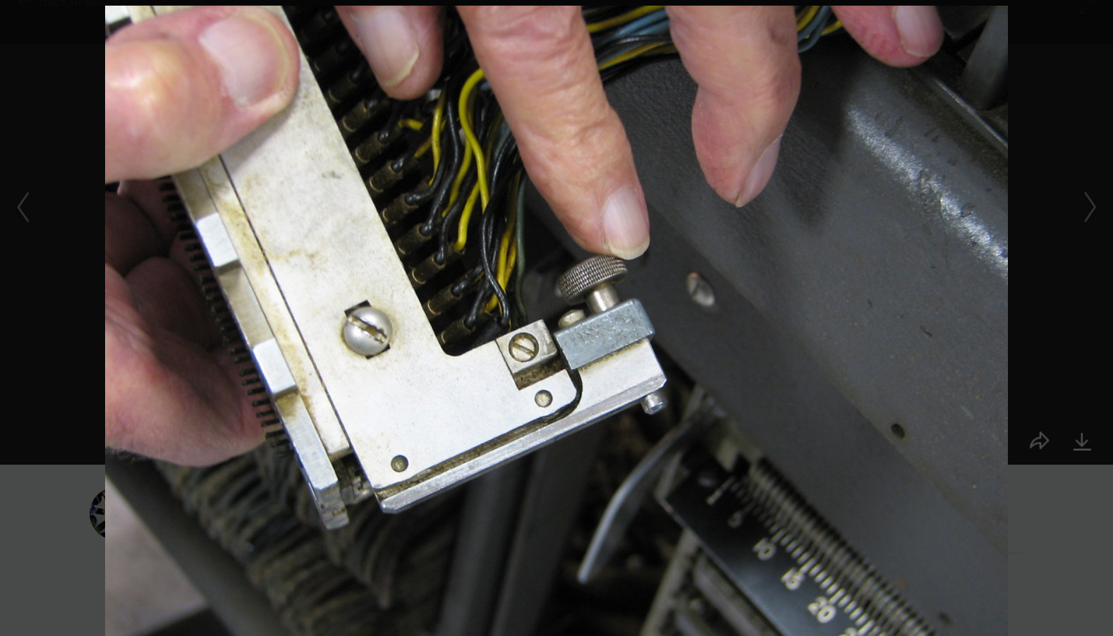
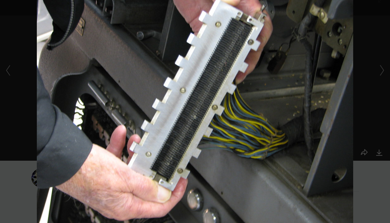
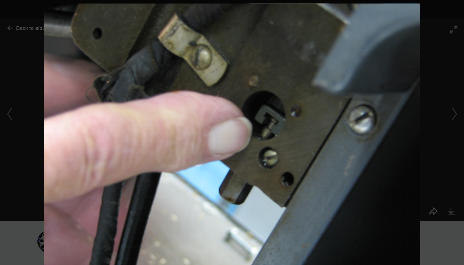
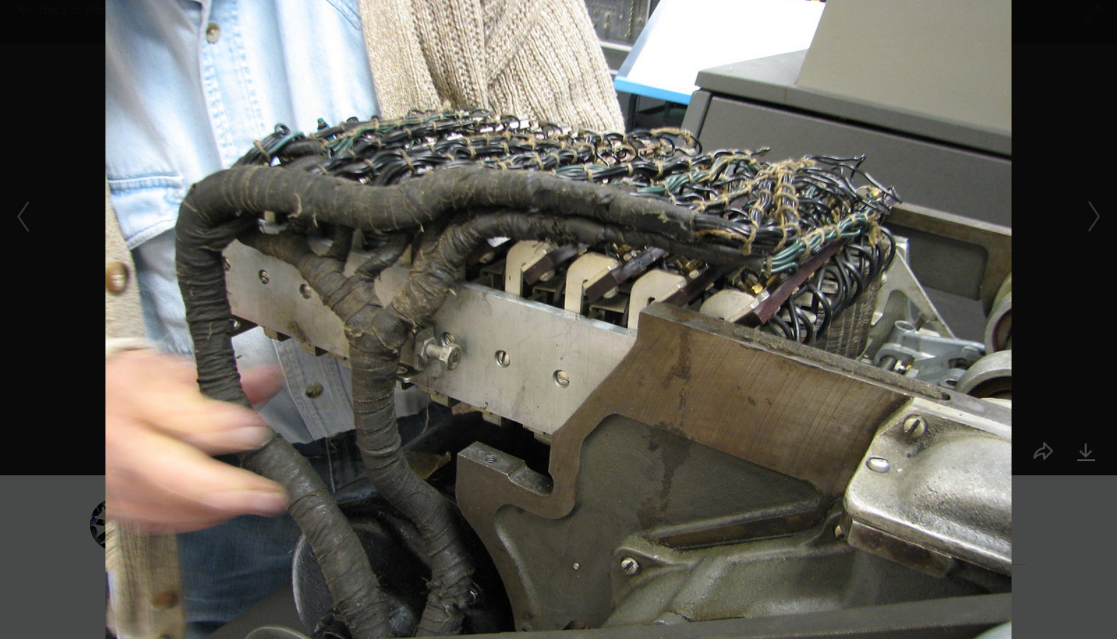
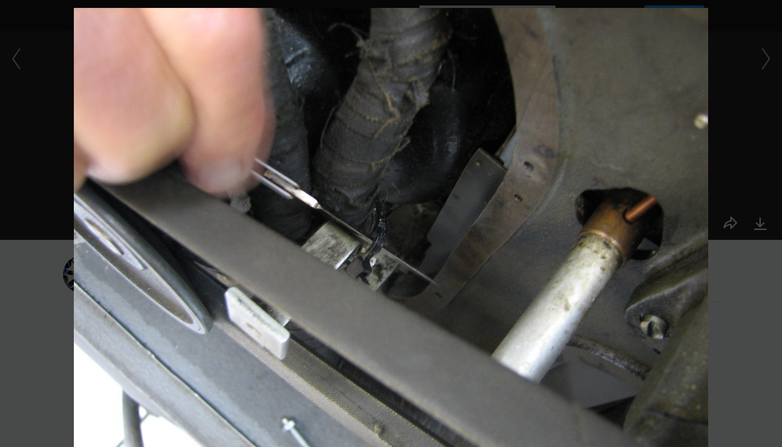
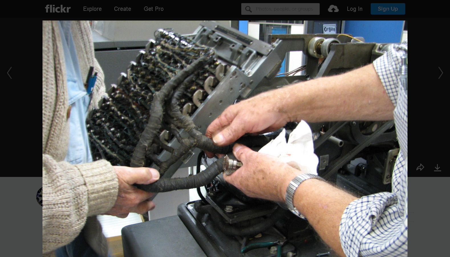
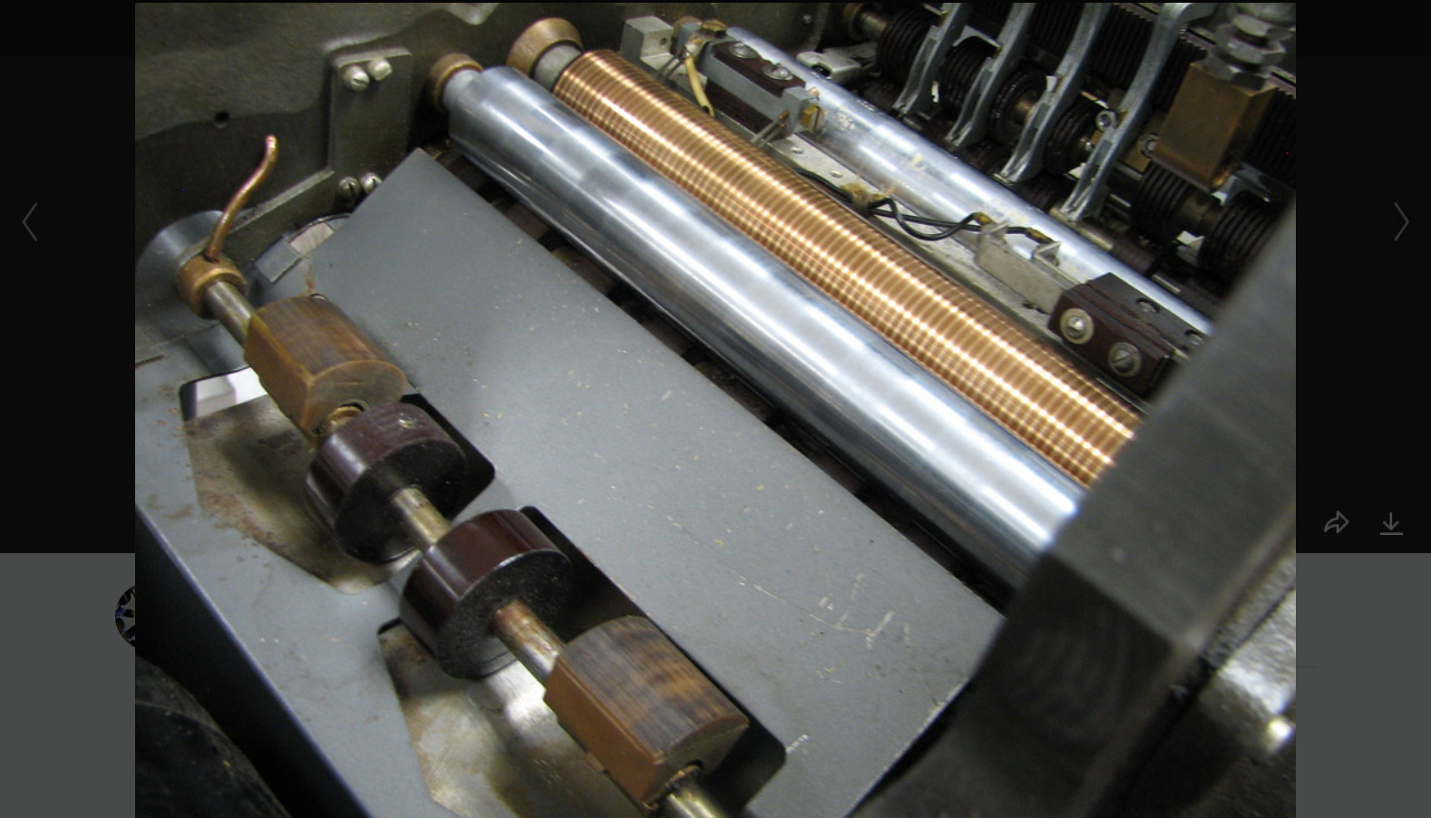
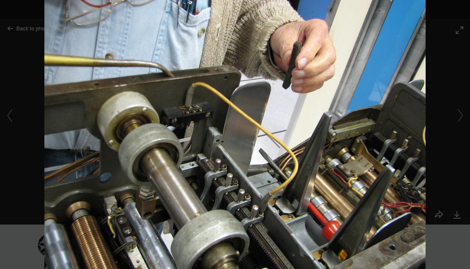
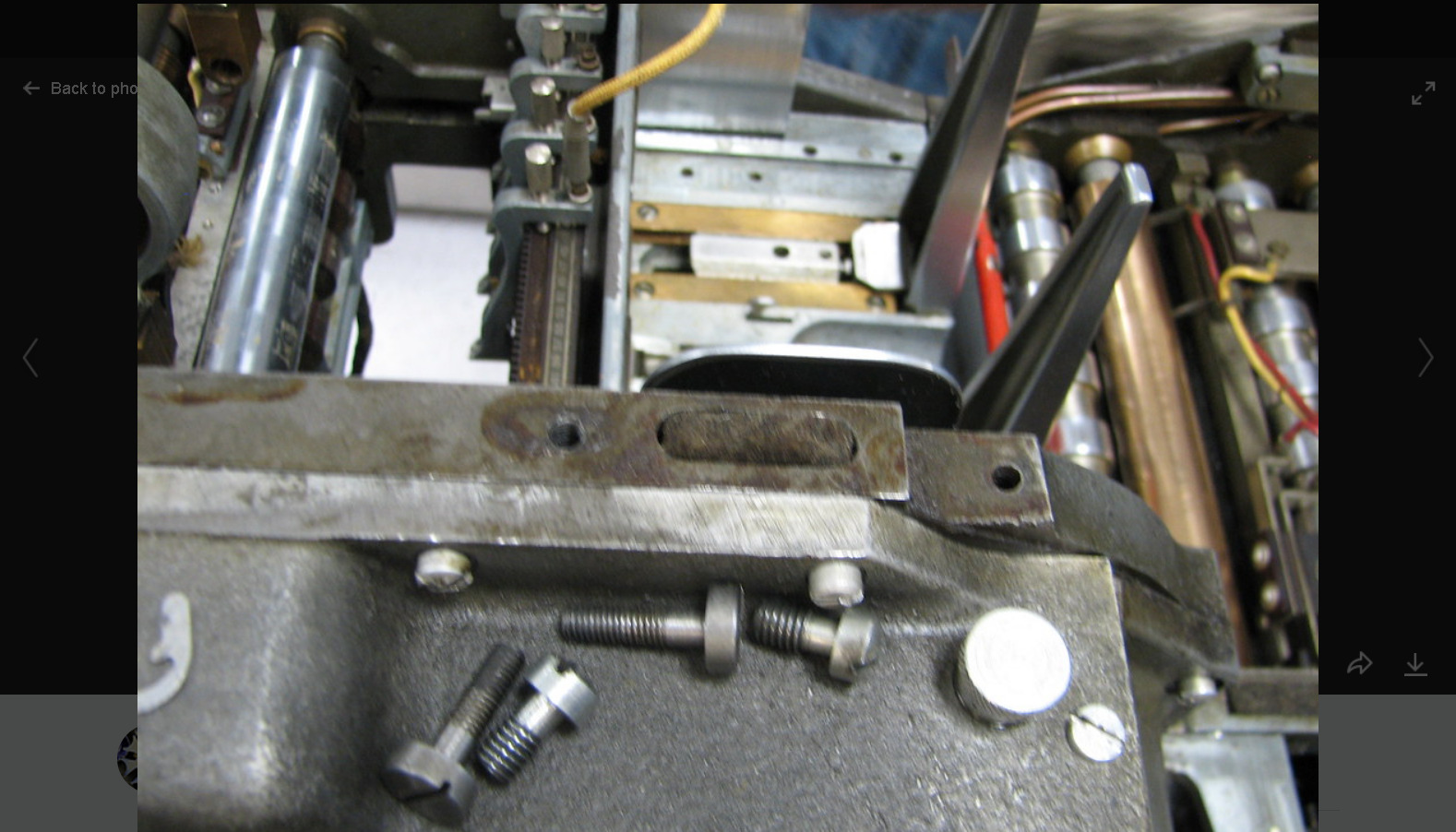
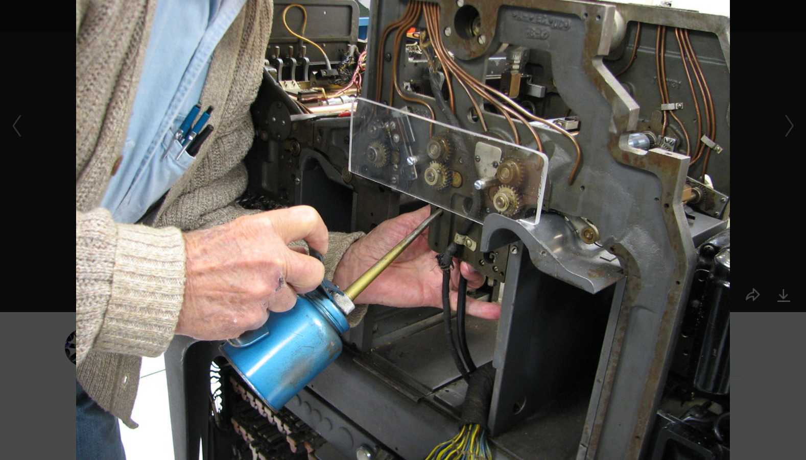
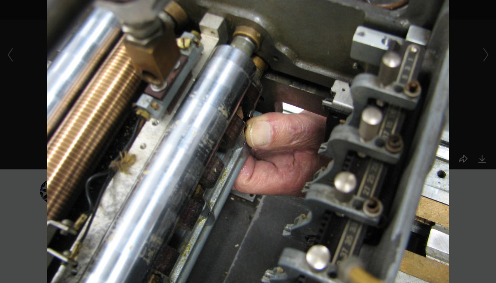
A step-by-step procedure for doing regular maintenance on an IBM 513 Reproducing Punch,
by Bob Erickson and Judith Haemmerle. Still in progress - captions not complete.
Some ideas may be applicable to the IBM 1402, one generation later.
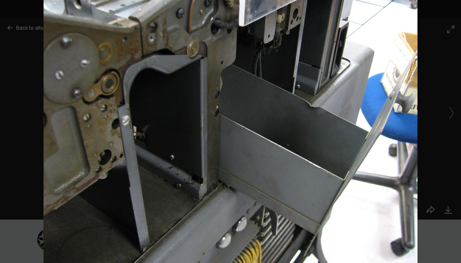
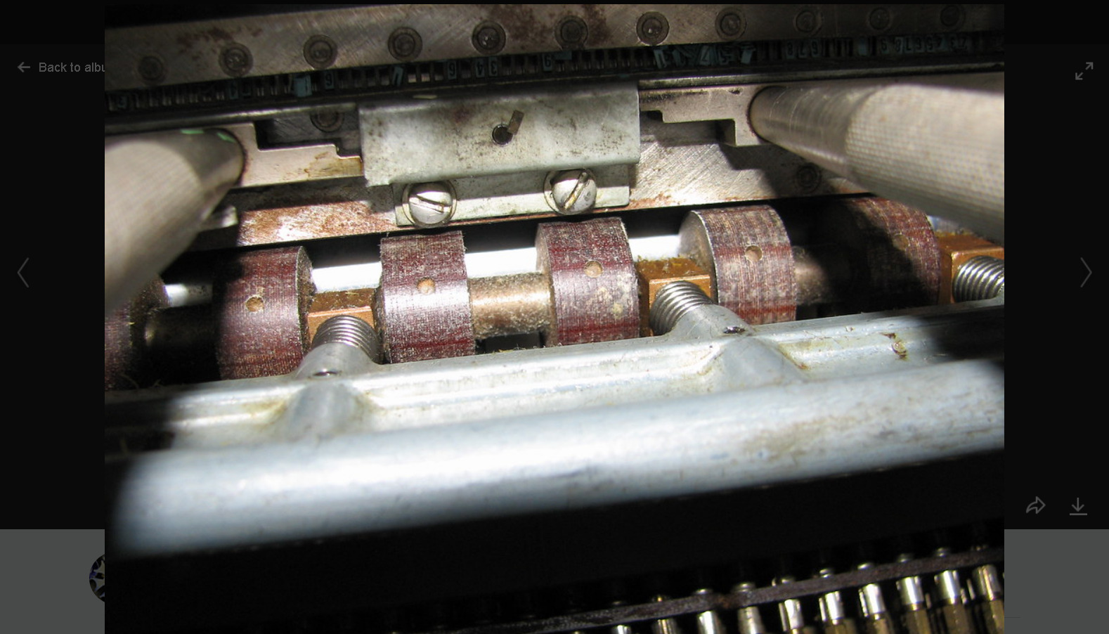
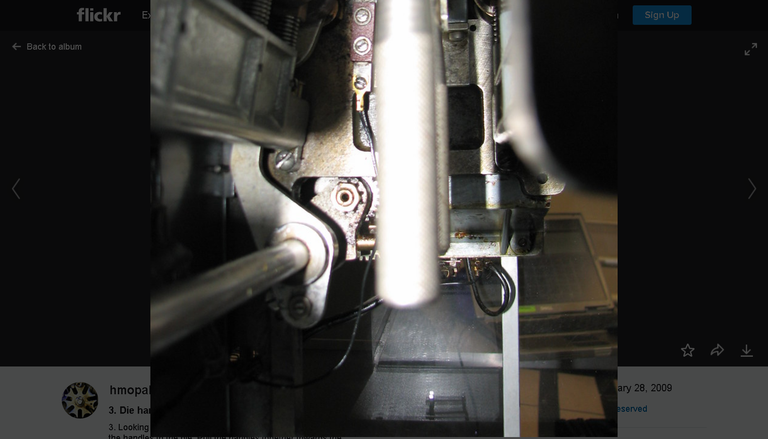
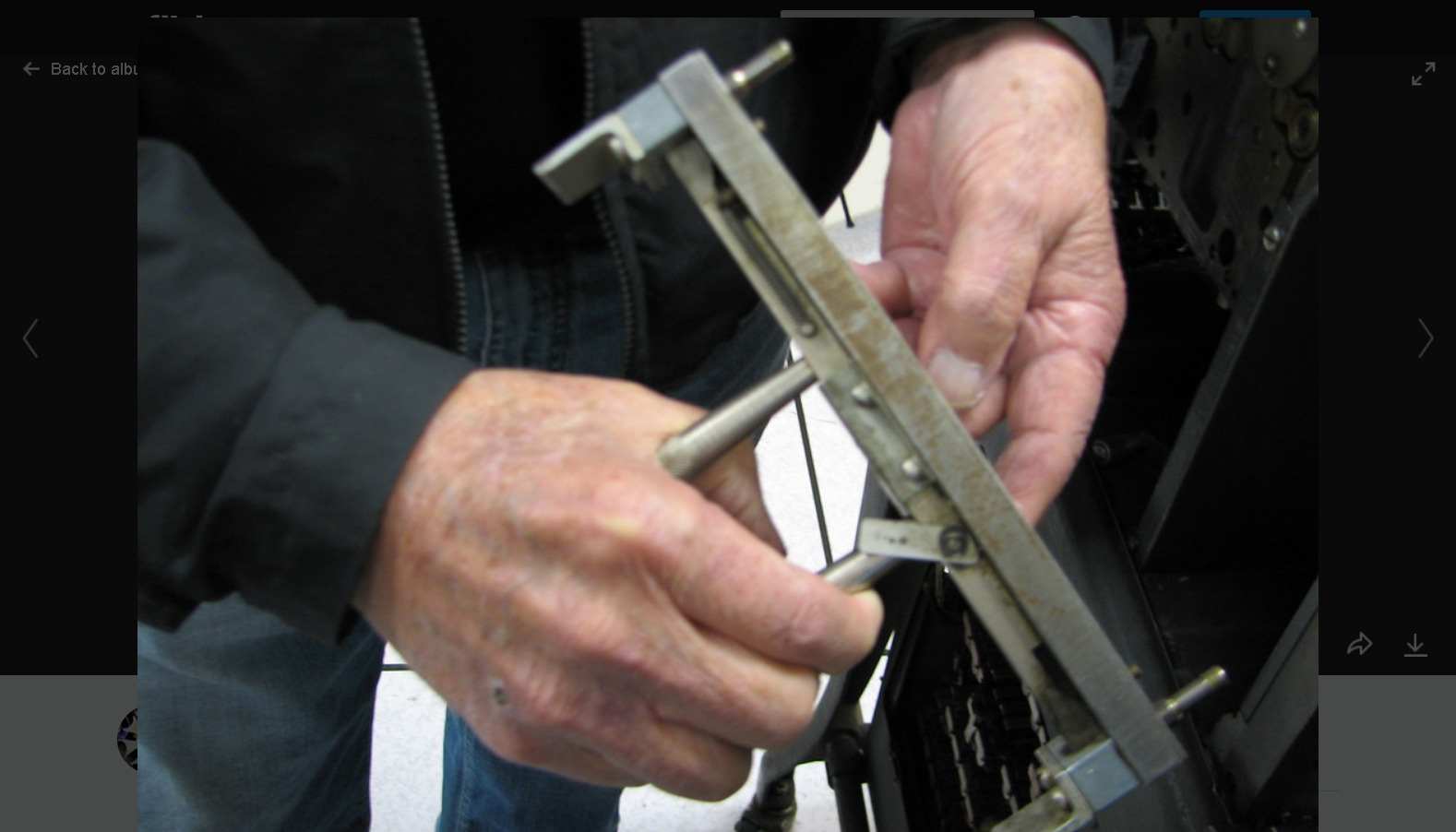
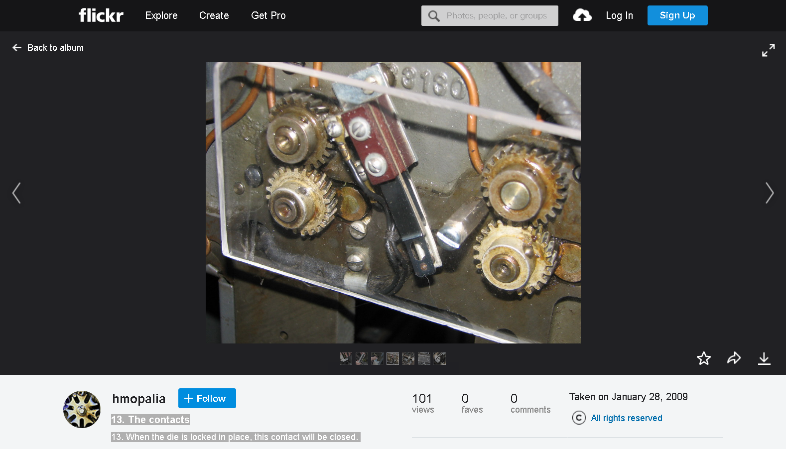
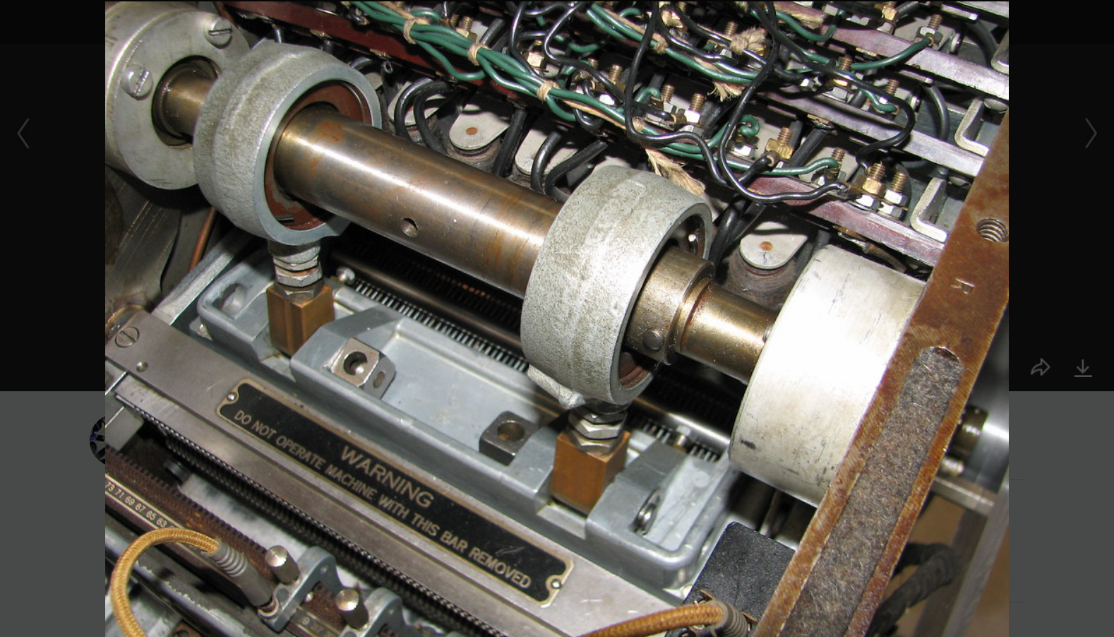
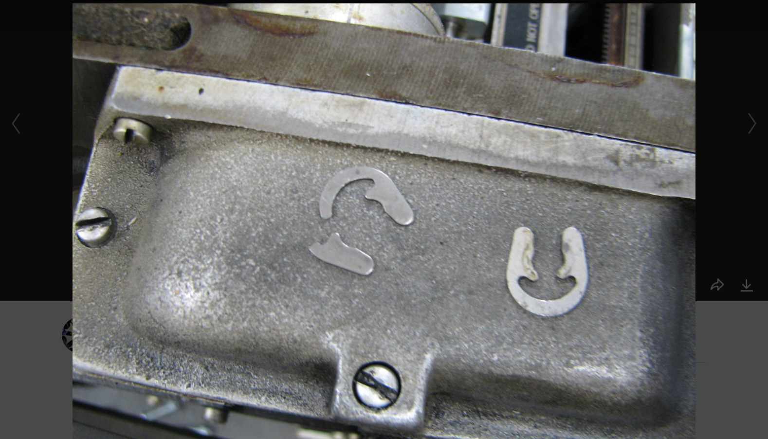
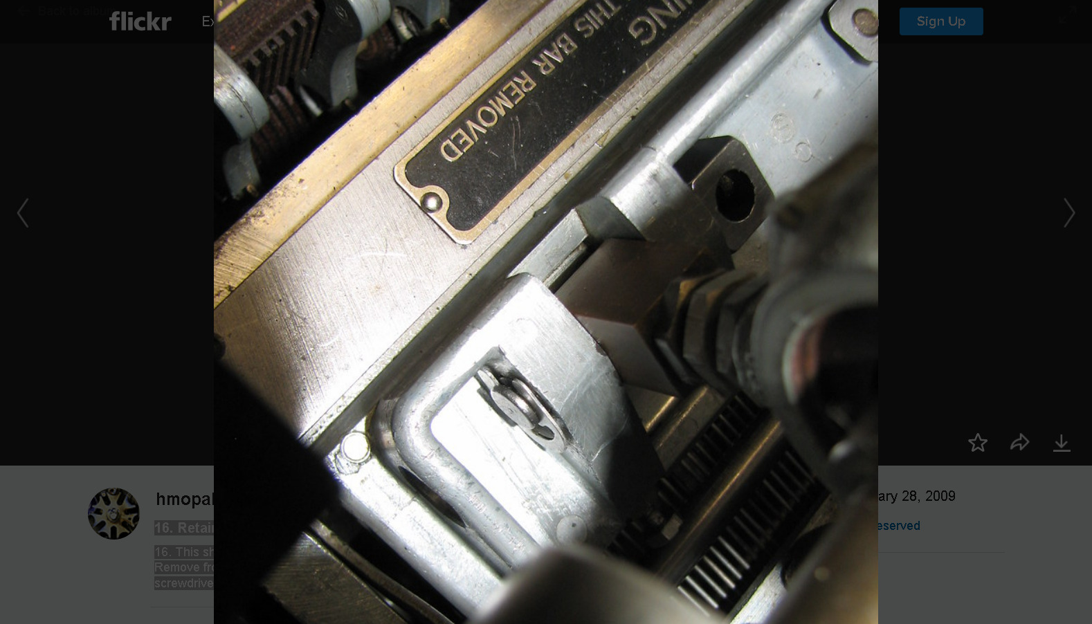
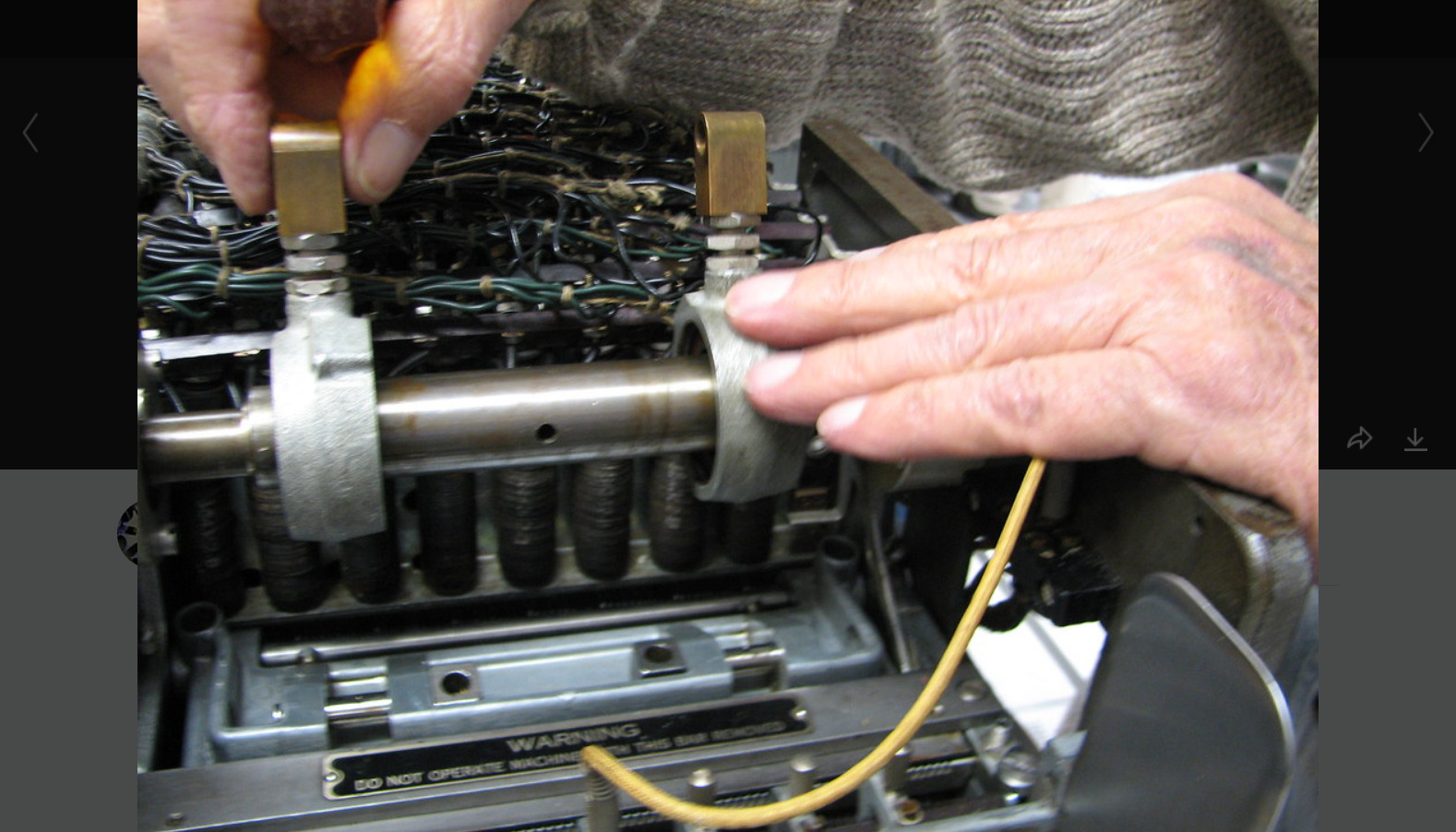
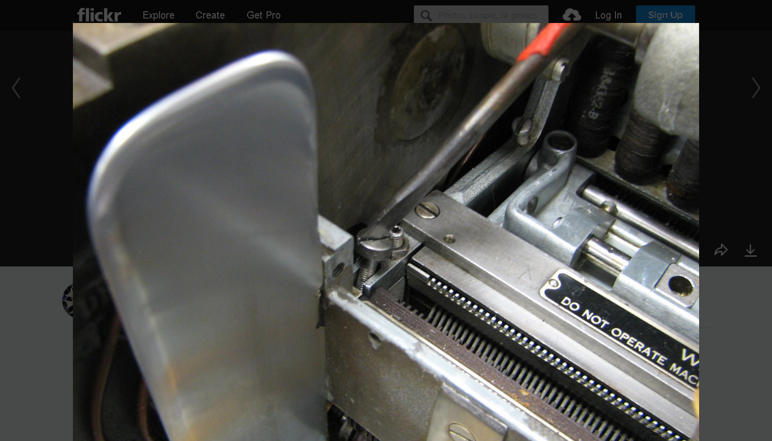
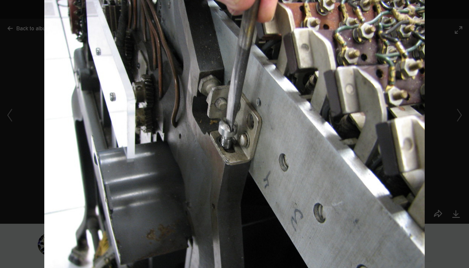
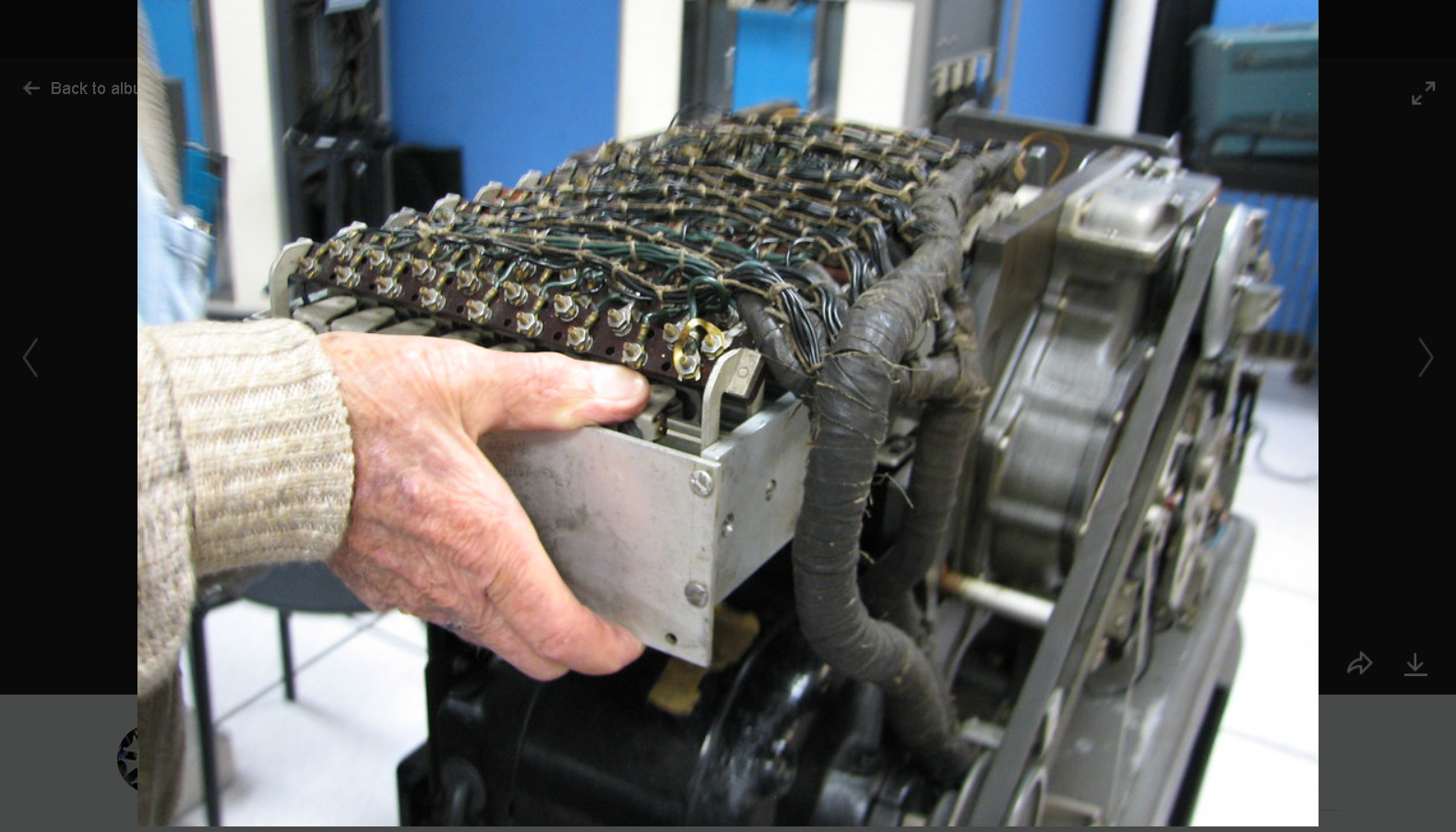
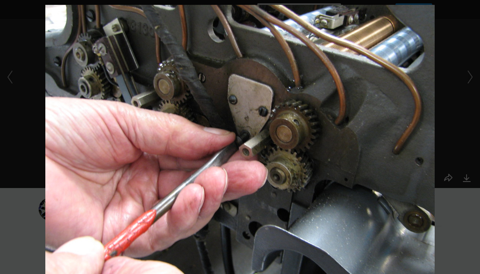
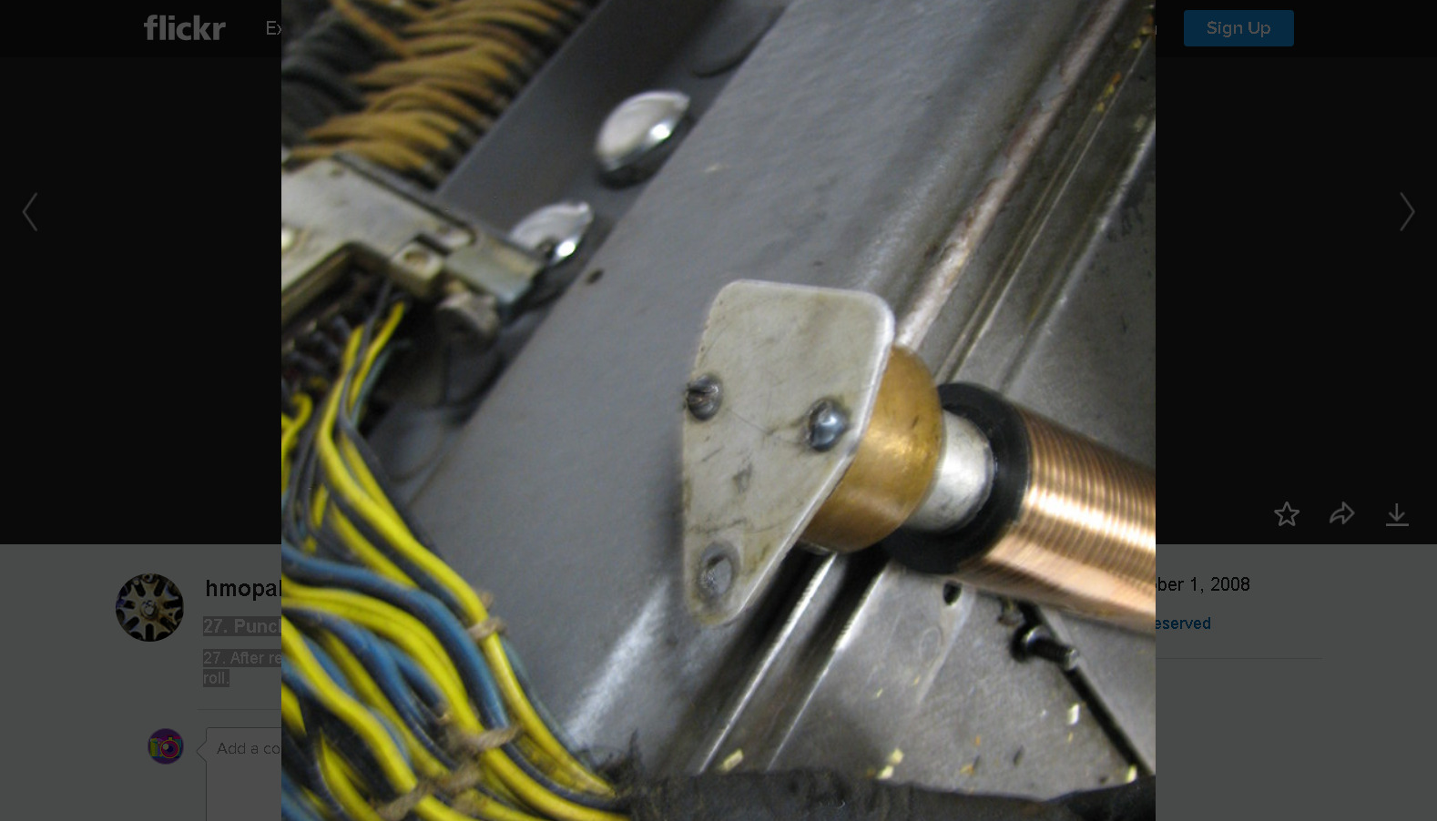
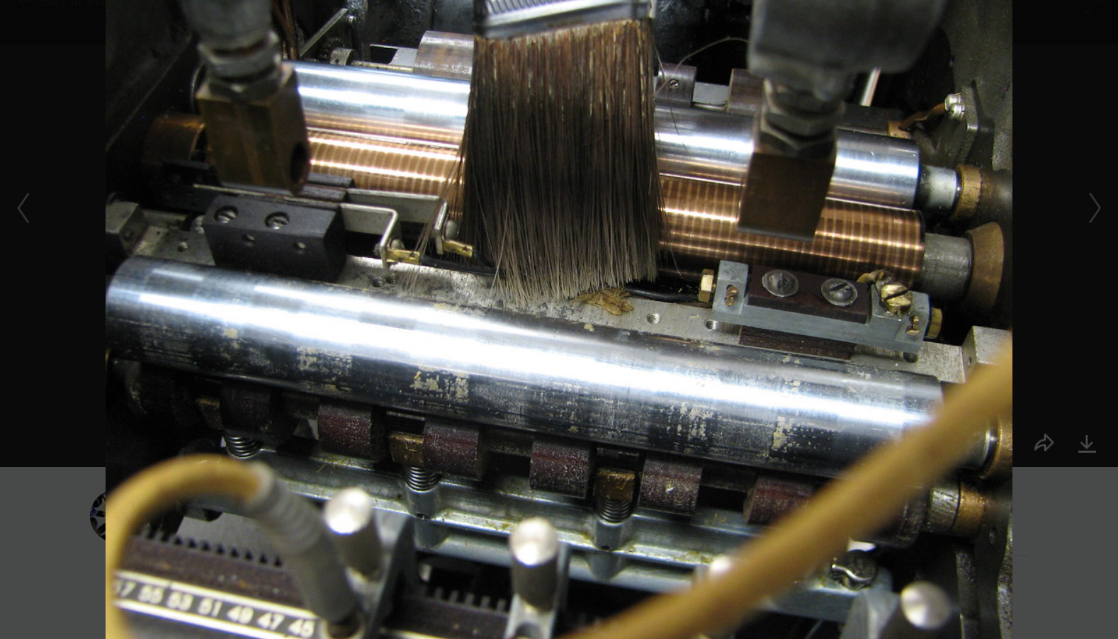
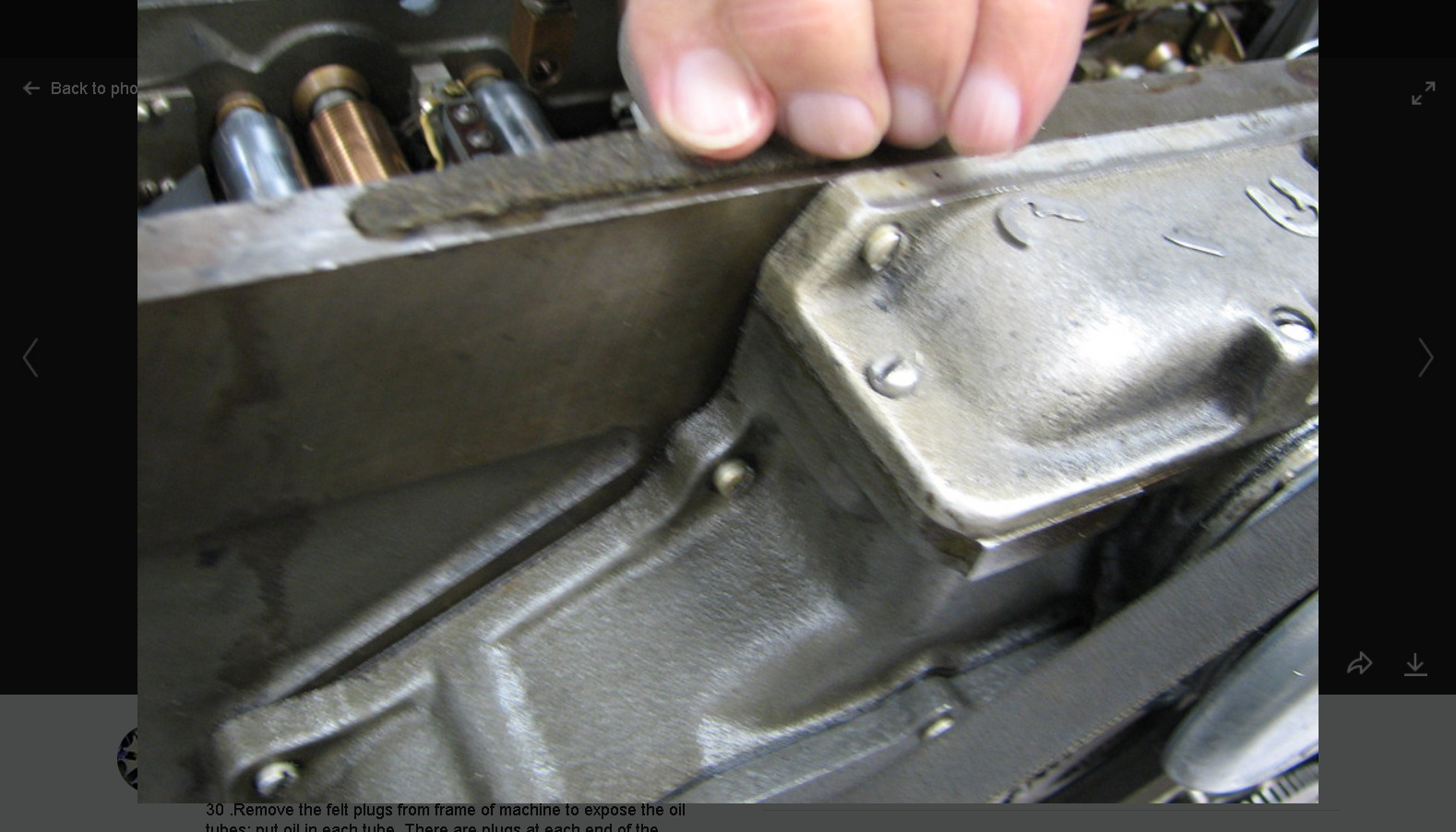
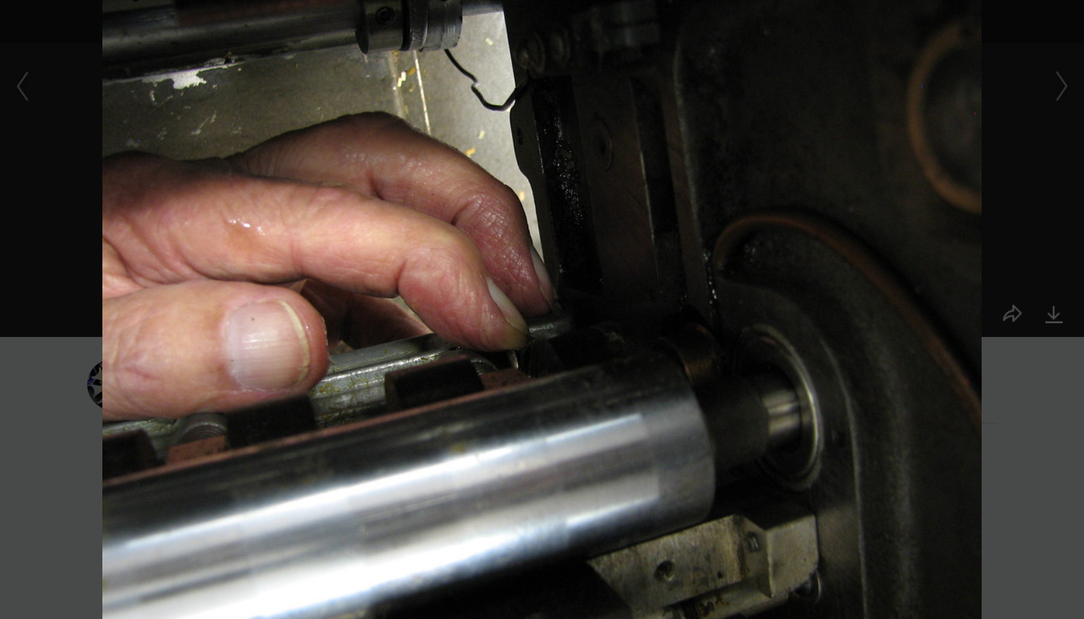
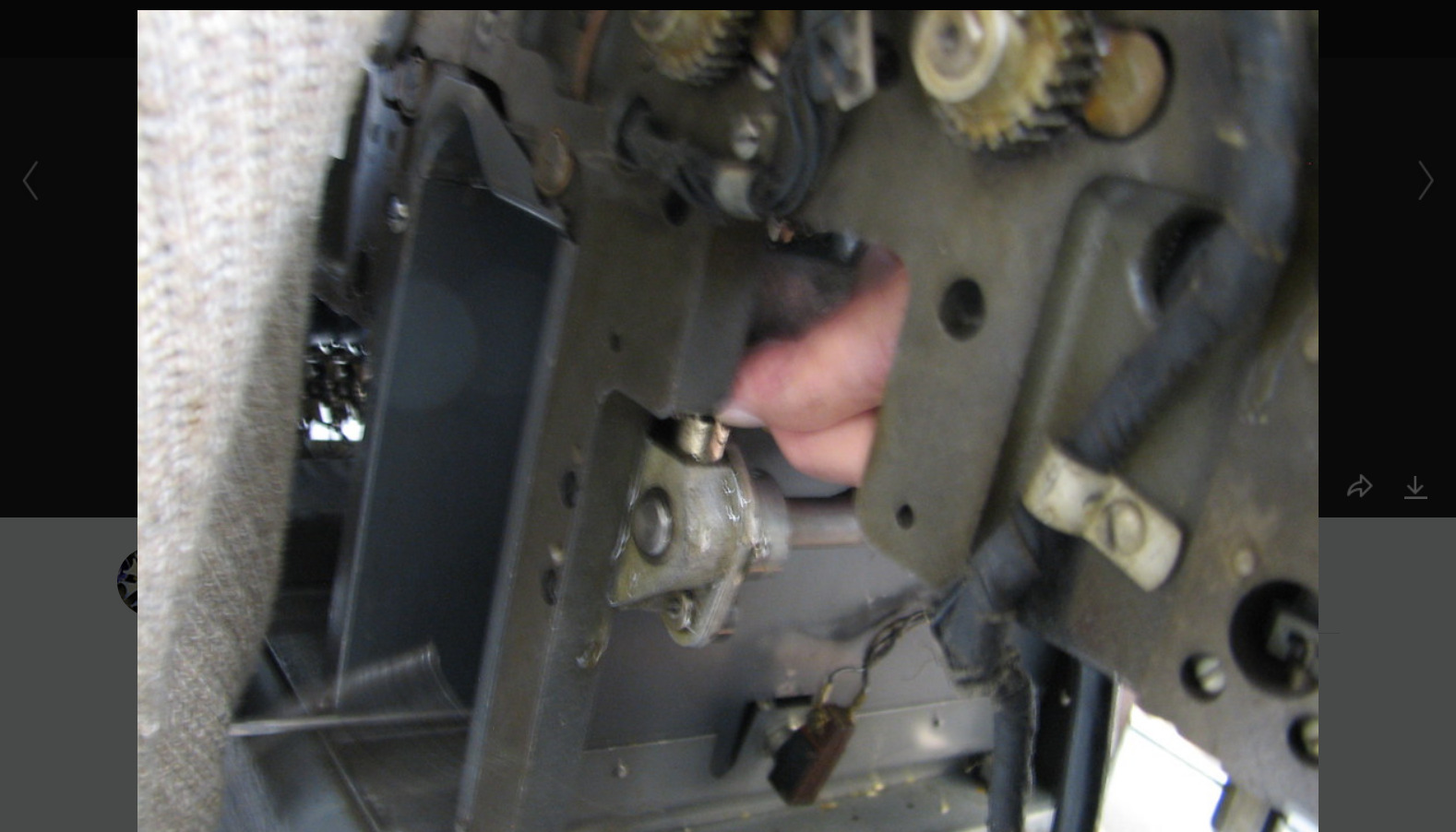
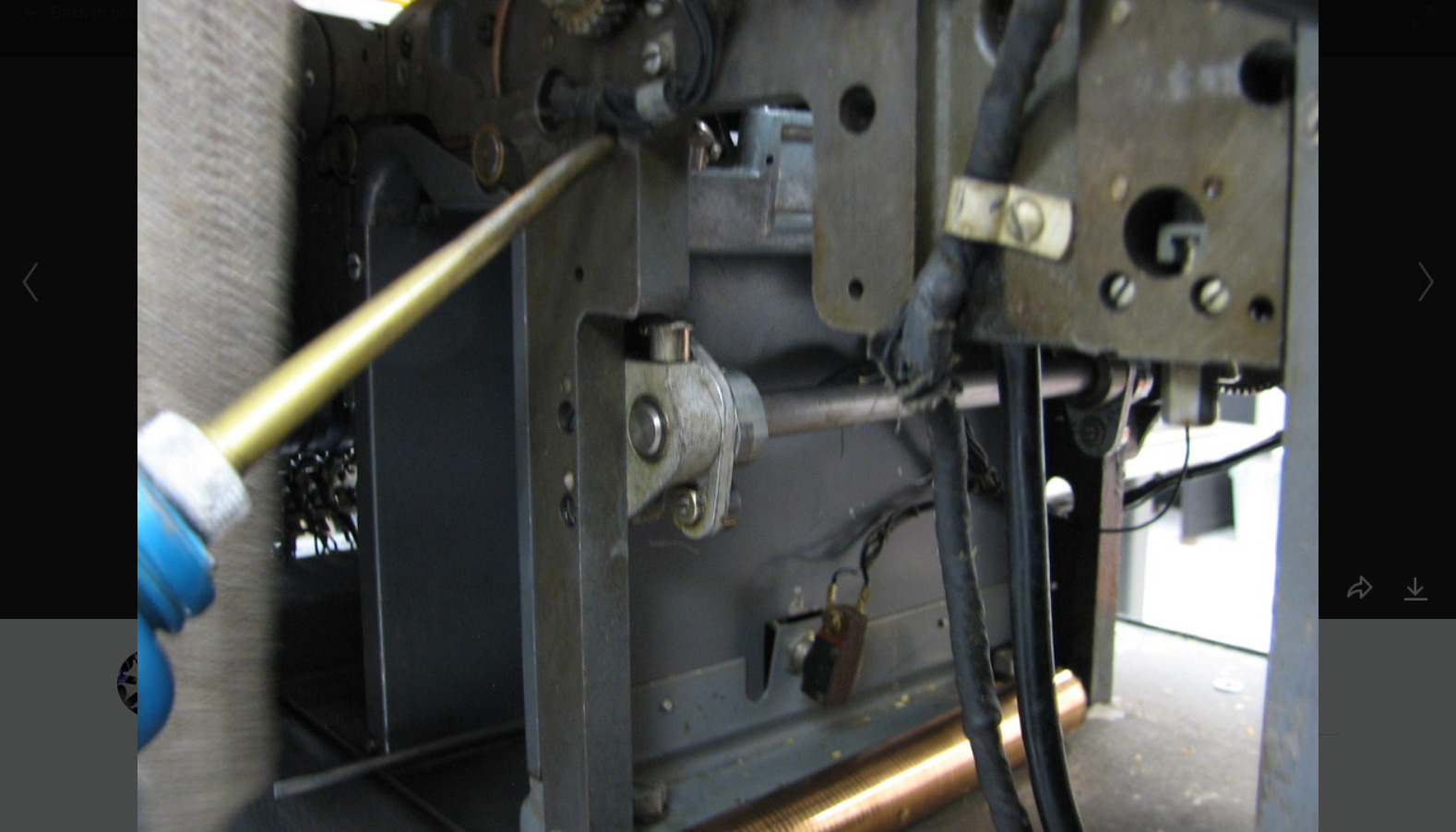
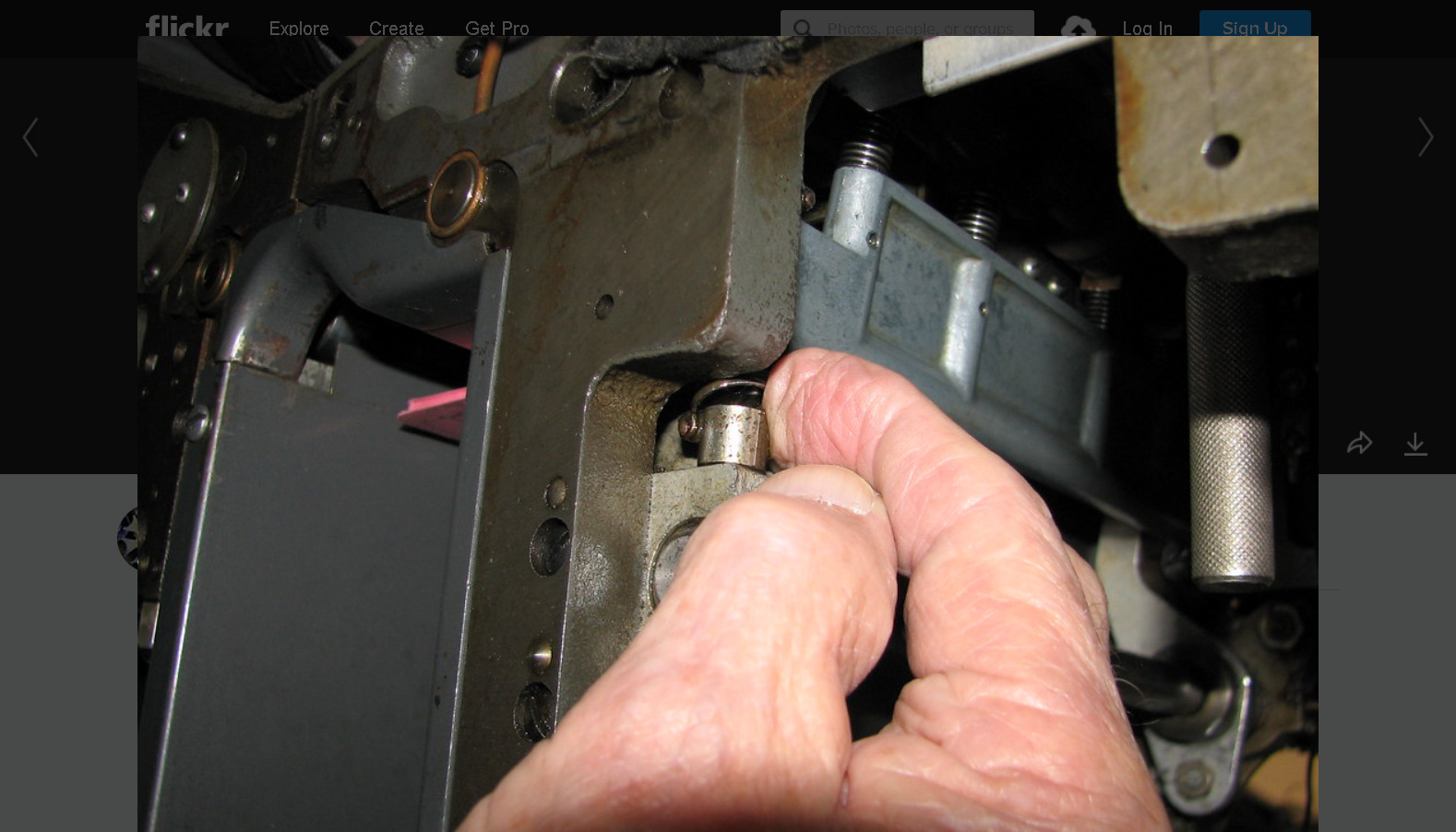
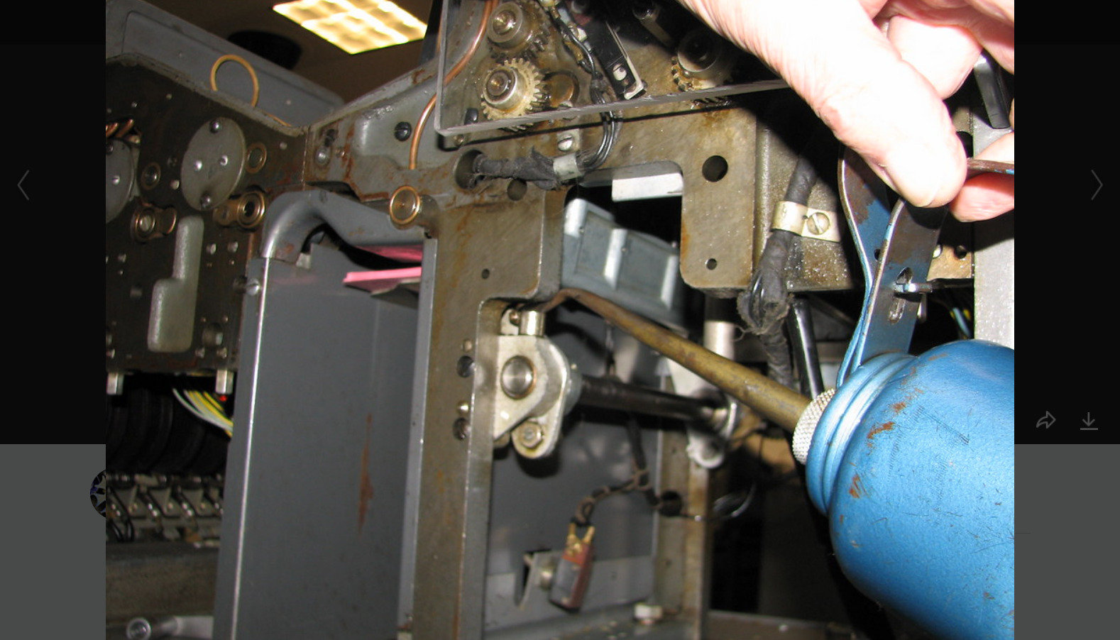
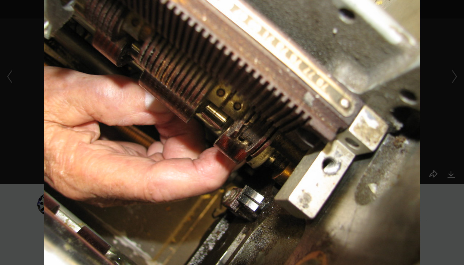
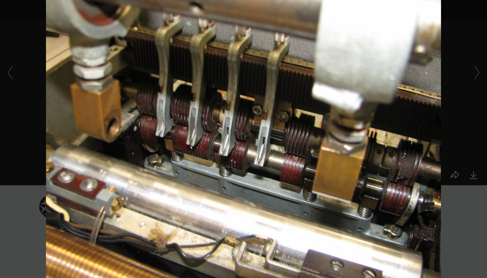
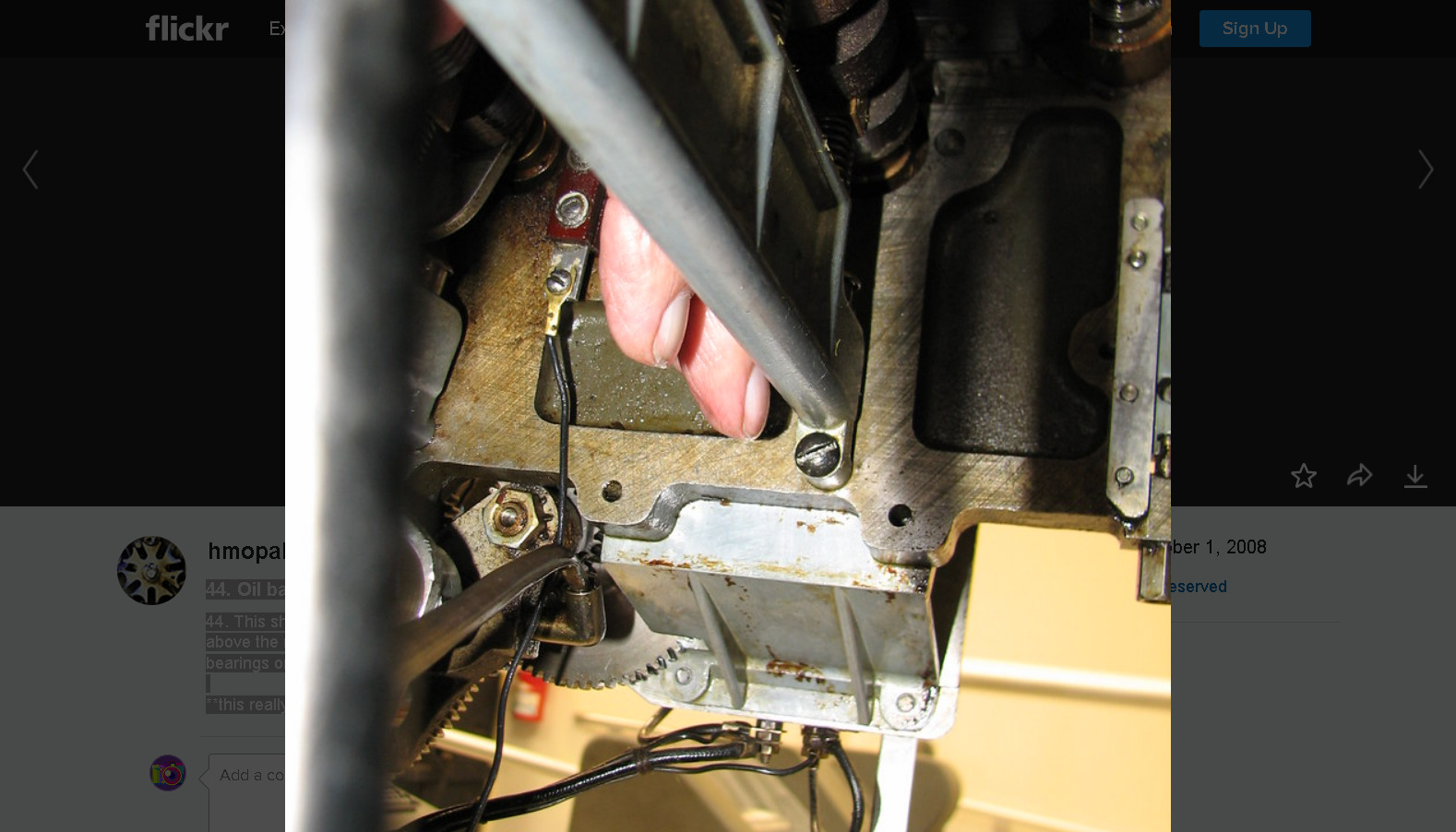
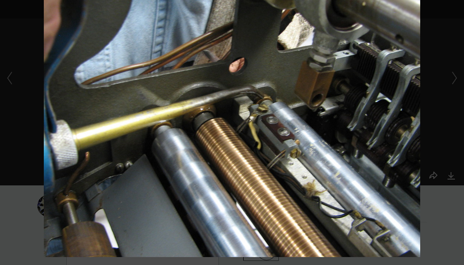
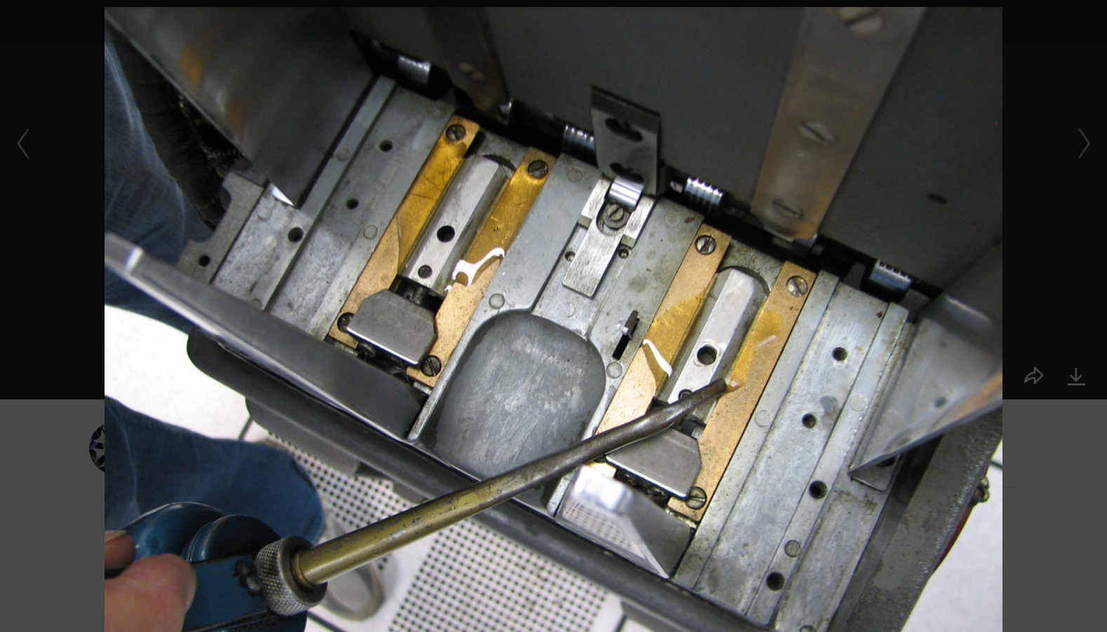
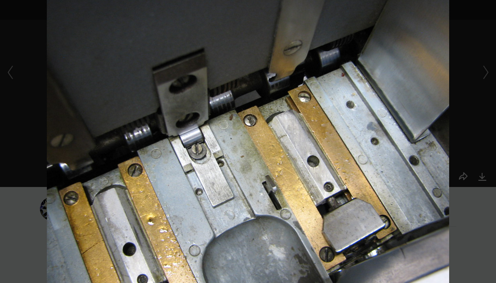
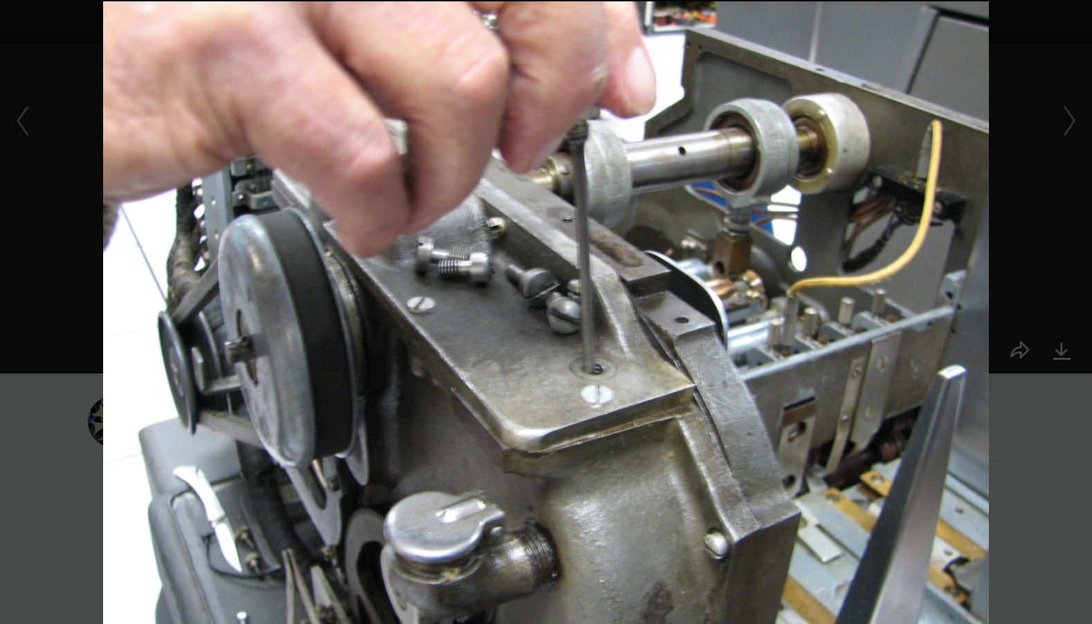
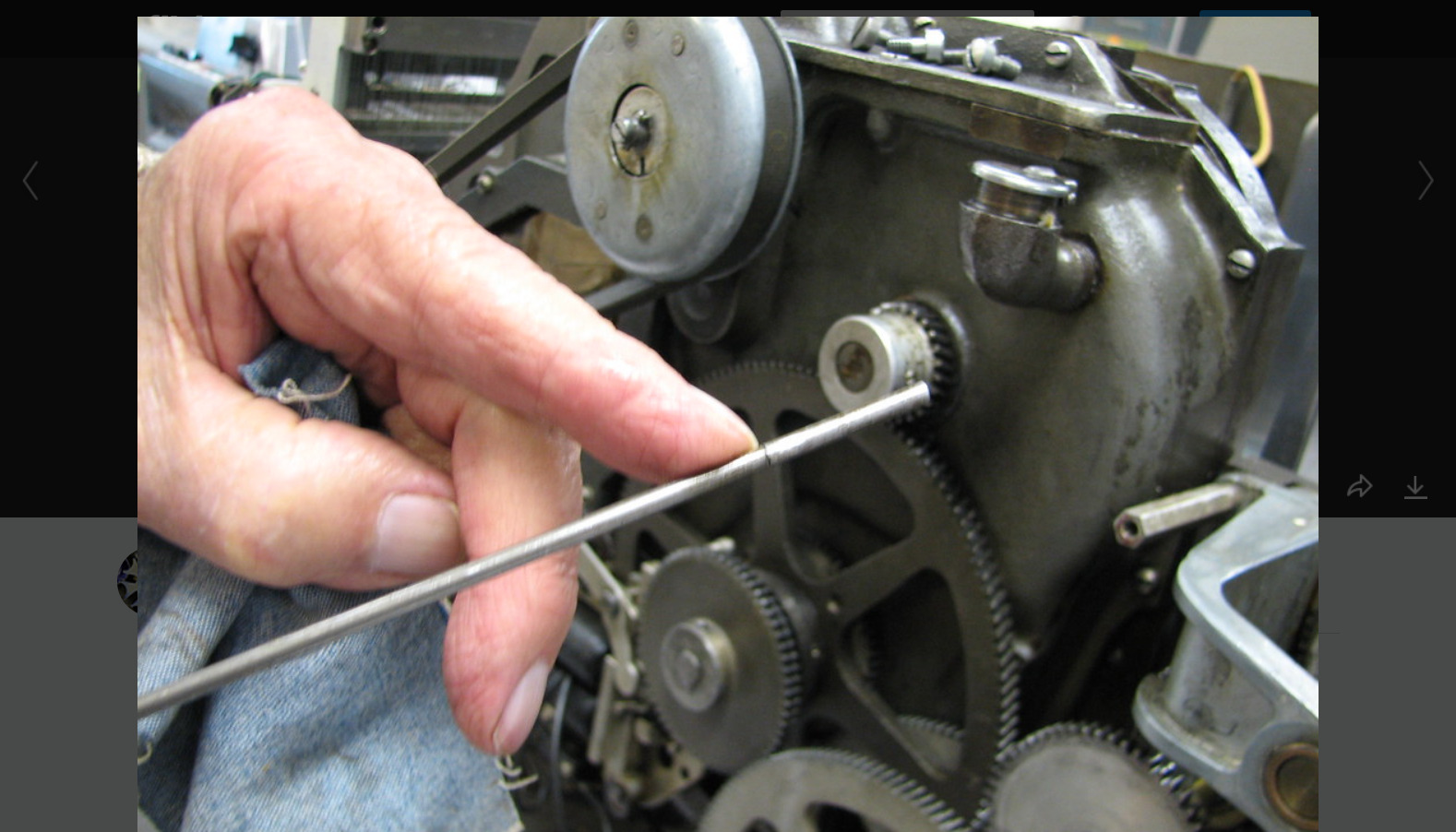
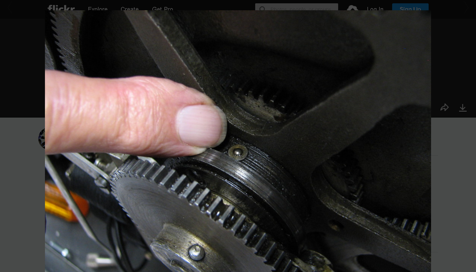
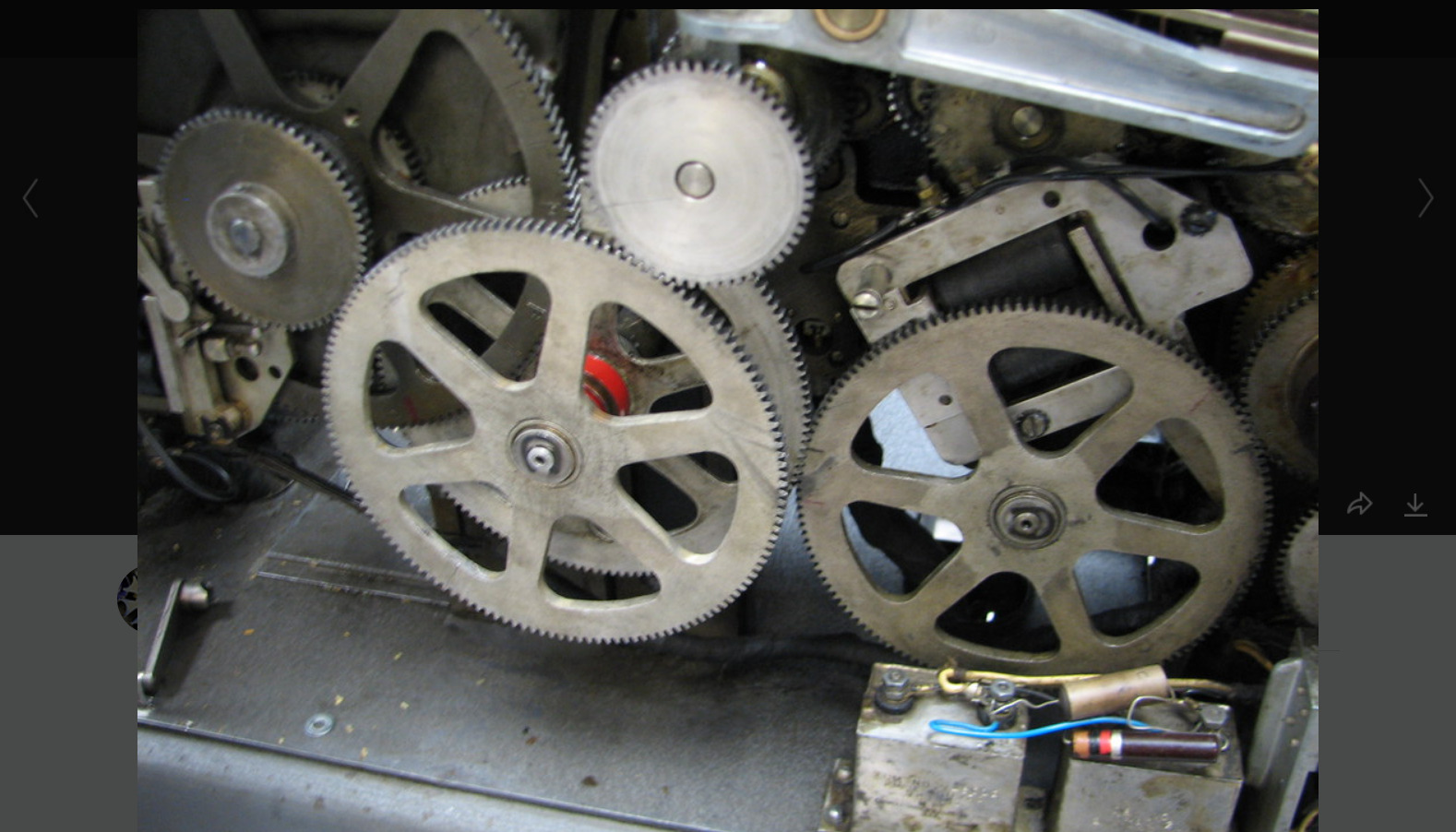
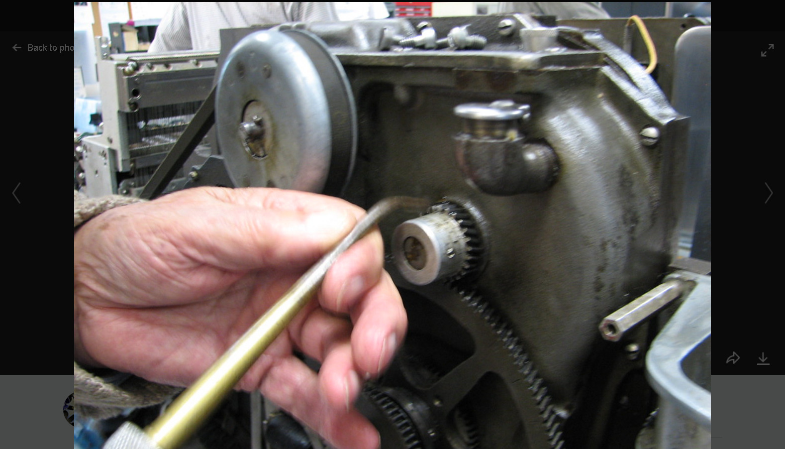
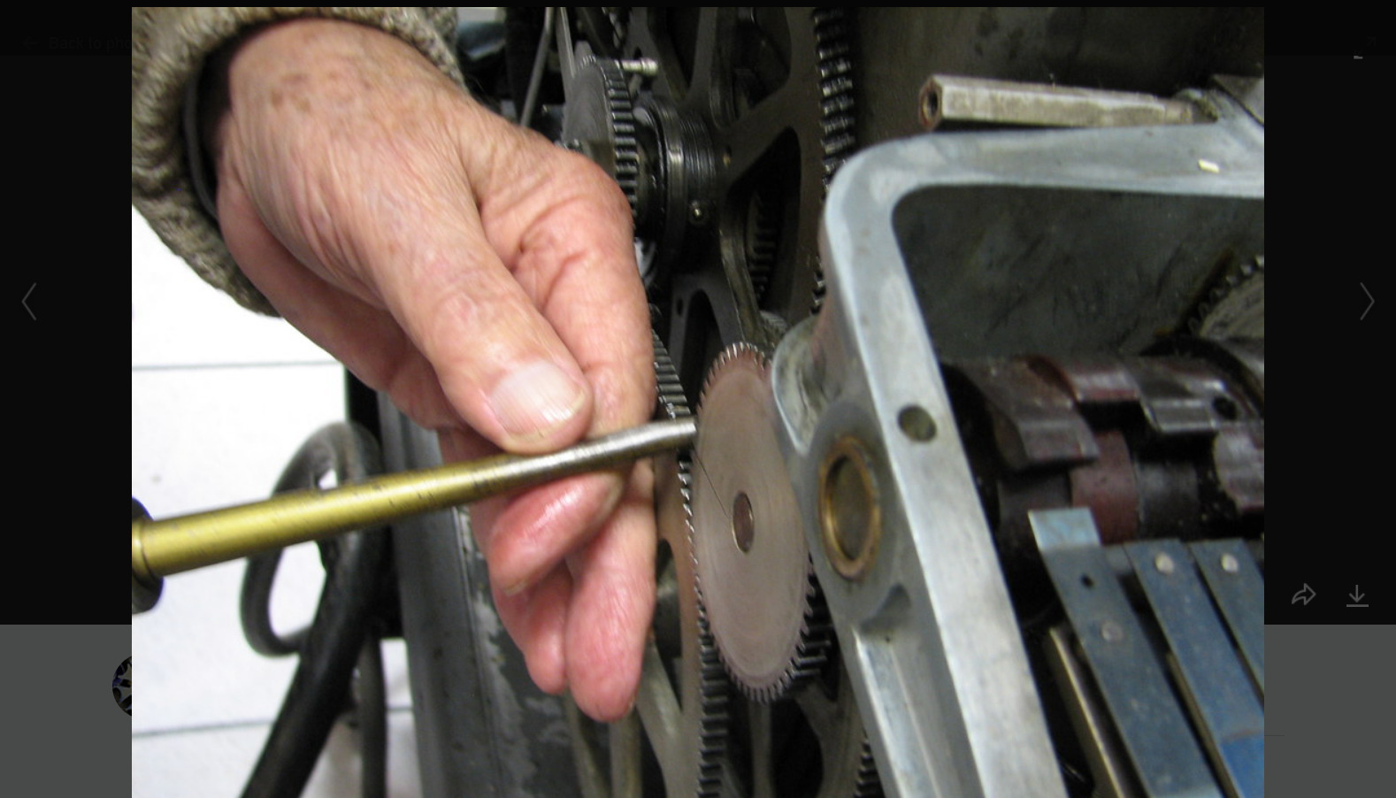
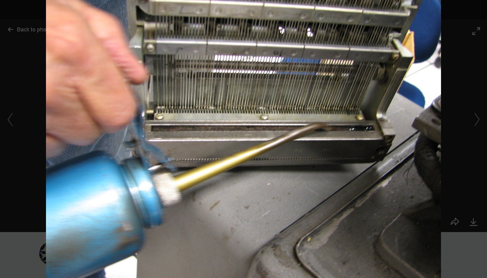
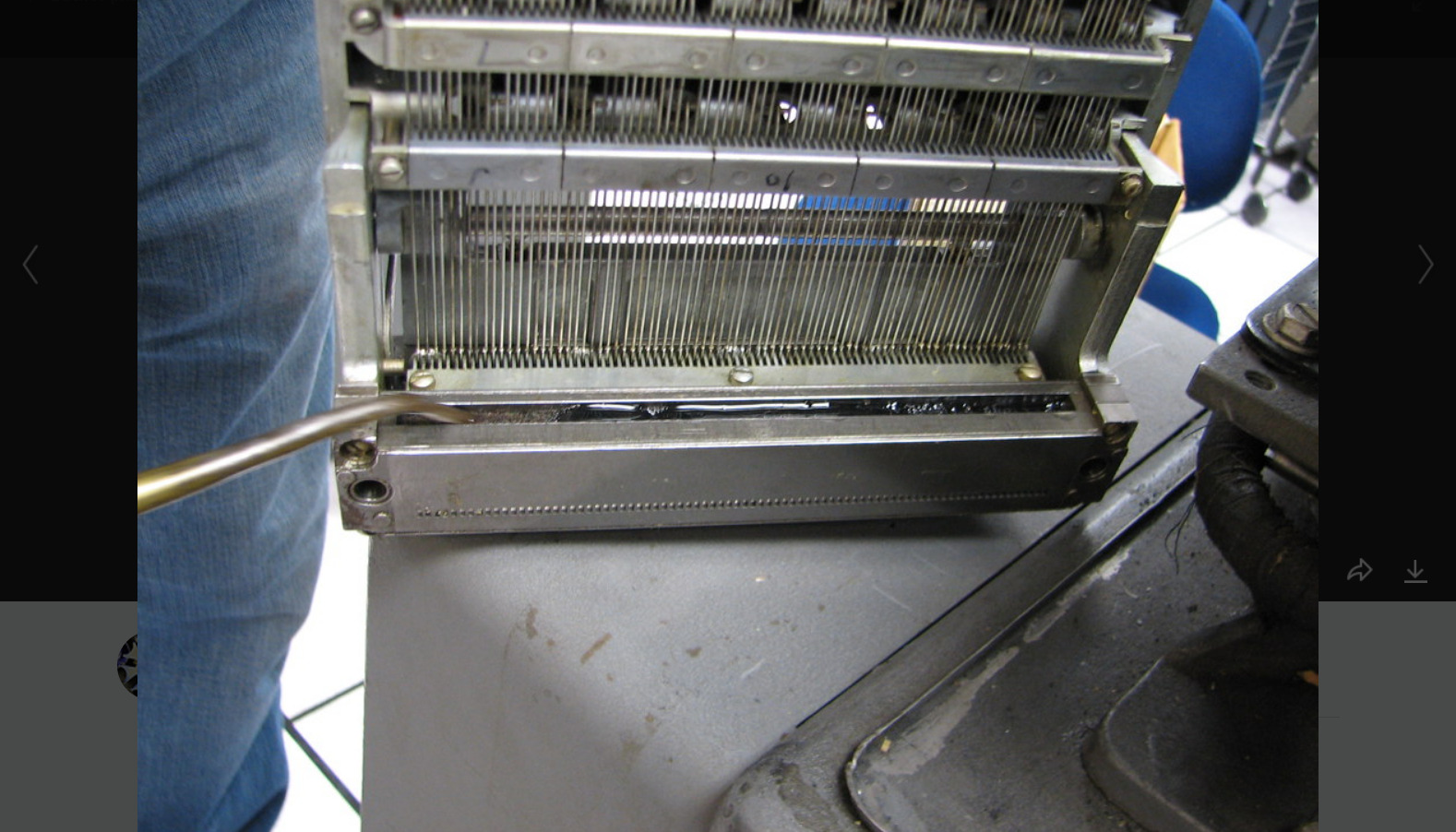
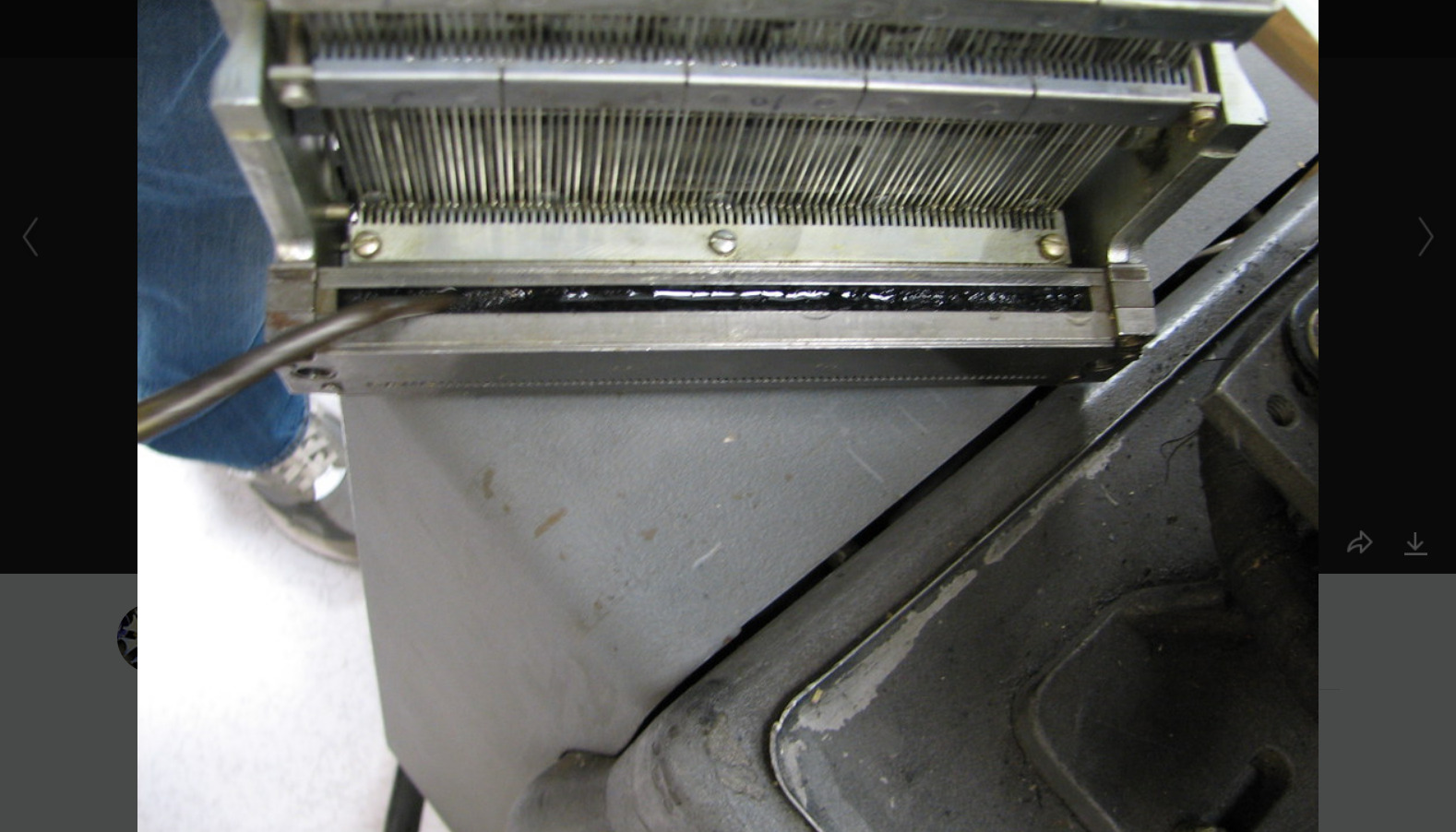
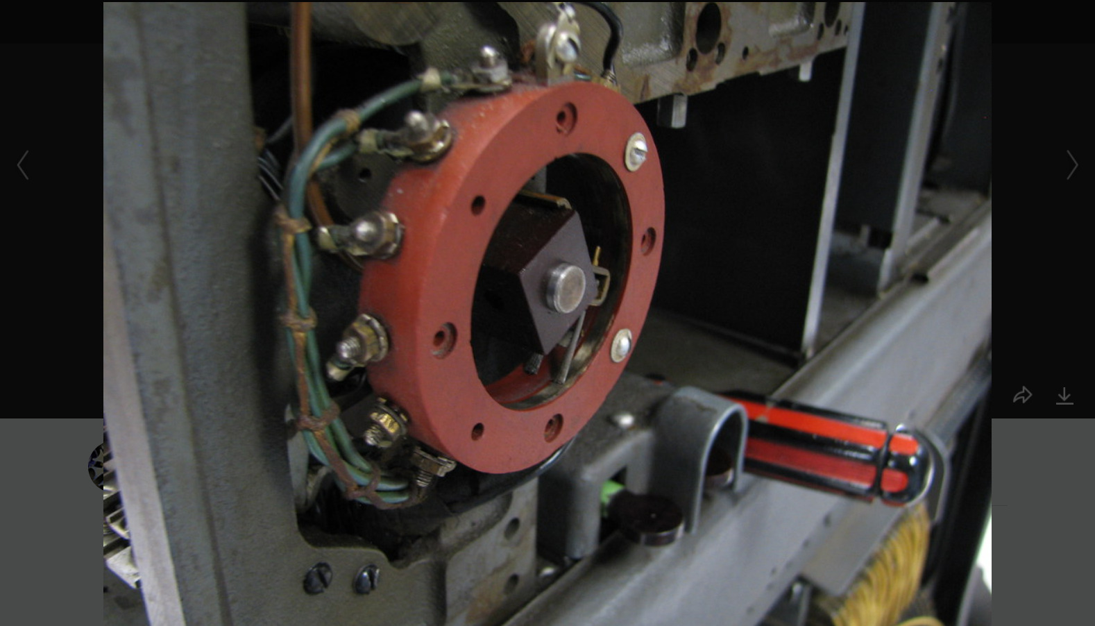
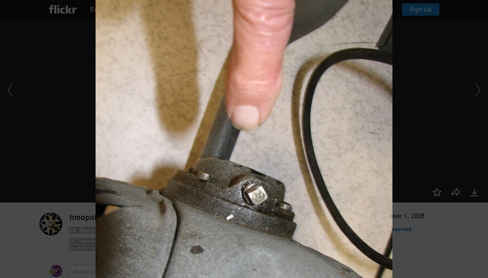
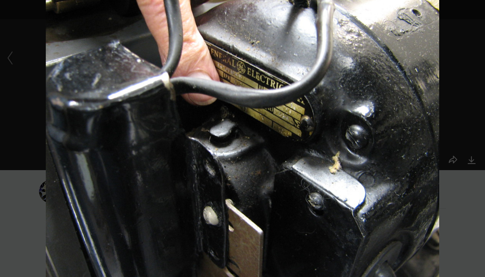
Album description A step-by-step procedure for doing regular maintenance on an IBM 513 Reproducing Punch, by Bob Erickson and Judith Haemmerle. Still in progress - captions not complete. Maintenance Schedule: Clean punch feed every 3 months or 1000 hours. Every three months, drop the read and check brushes, remove the rollers and oil through holes in the frame as in 14a on. Clean read unit every 6 months or 3000 hours. Oil gear train with every cleaning. Use IBM 10 or equivalent for all lubrication unless otherwise specified. Once a year, put oil in the motor cups and alemite (?) in the motor-generator. After maintenance, start up the 513 and check hole registration. It may be necessary to adjust the magnet unit placement. |