Return to 729 tapes
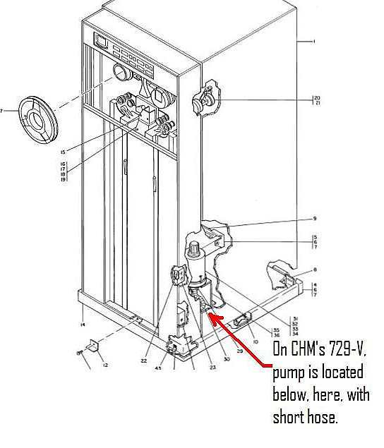
Assembly of IBM 729-V Tape Drive Vacuum Pump
(5 stage, centrifugal, 3 phase motor driven)
(Iggy 05/13/2015)
Ignacio Menendez
ignalic at yahoo dot com
|
|
Table of Contents
- Parts Inventory:
- Assembly Instructions
- Proposed Theory of Operation:
- Findings, Anecdotes, Wisdom, etc
- Epilog to 729 Vacuum Pump re-assembly - 7/1/2015
- Flurry of e-mails in Oct 2019
Parts
Inventory:
-
- 3 phase small motor windings’ assembly with plug
-
- Base casting
-
- Round cylindrical shroud with 3 clasps that hold #19 with lock
washers and nuts
-
- 6 small screws to attach #4 to #3
-
- 4 screws to attach #1 to #2
-
- Motor shaft with molded “squirrel cage”
-
- small bearing for motor end of shaft
-
- large bearing for shaft support on #2
-
- large retaining “C” clip to hold large bearing and
shaft in #2
- -
spacers, as needed, to eliminate play of motor shaft once inserted
and held by #9
- -
1/16” spacer
- -
5 rotating vanes with large inside diameter (ID) (rotor)
- -
5 static baffle vanes with small ID (stator)
- -
1 narrow spacer band
- -
5 wide spacer bands
- -
5 ‘sand-clock’ shape spacers with small metal pin on one
end, ID of motor shaft
- -
final truncated cone spacer with KEY for motor shaft
- -
Large head screw to hold all #12s and #16s unto motor shaft
- -
End cover with 90º elbow vacuum hose intake
- -
4 large hex/slot head screws with locking washers
- -
External vacuum hose, with two metal clamps that attach #19 to vac.
column plenum
|
Assembly
Instructions (rotors and stators marked with number and rotation
arrow)
- -insert #8 bearing to #6 motor shaft
- -insert #6 shaft, including #7 bearing into #2 casting
- -insert #9 “C” clip to #2 casting to retain motor shaft with minimal end play (if unable to seat “C” clip totally in the trench,
.
loosen the screws ( a couple of turns) that secure the back plate holding the large bearing from behind the casting, insert
. the “C” clip, retighten the screws that were loosened for the insertion of the “C” clip.
- -Attach #1 motor to #2 casting with #5 screws
- -Attach #3 shroud to #2 casting using #4 small retaining screws
- -Insert and seat #14 narrow band in #3 seated tight to #2 casting
- -insert #11 spacer to motor shaft
- -insert #13 stator10 all the way down to rest on #11 spacer band installed in previous step (large OD of stator facing down)
- -insert #15 wide spacer band, ensure tight seating on stator inserted in previous step
- -insert #16 spacer on motor shaft, with metal pin sticking up (to open end where components are being inserted)
- -insert #12 rotor9 to motor shaft, ensure pin from spacer below fits in hole of rotor, make sure rotor spins with shaft freely
- -insert #13 stator8 to motor shaft, seat tight on wide spacer band installed in step 9 above (large OD of stator facing down)
- - insert #15 wide spacer band, ensure tight seating on stator inserted in previous step
- -insert #16 spacer on motor shaft, with metal pin sticking up and having previous spacer’s pin inserted in hole of this one.
- -insert #12 rotor7 to motor shaft, ensure pin from spacer below fits in hole of rotor, make sure rotor spins with shaft freely
- -insert #13 stator6 to motor shaft, seat tight on wide spacer band installed in step 9 above (large OD of stator facing down)
- - insert #15 wide spacer band, ensure tight seating on stator inserted in previous step
- -insert #16 spacer on motor shaft, with metal pin sticking up and having previous spacer’s pin inserted in hole of this one.
- -insert #12 rotor5 to motor shaft, ensure pin from spacer below fits in hole of rotor, make sure rotor spins with shaft freely
- -insert #13 stator4 to motor shaft, seat tight on wide spacer band installed in step 9 above (large OD of stator facing down)
- - insert #15 wide spacer band, ensure tight seating on stator inserted in previous step
- -insert #16 spacer on motor shaft, with metal pin sticking up and having previous spacer’s pin inserted in hole of this one.
- -insert #12 rotor3 to motor shaft, ensure pin from spacer below fits in hole of rotor, make sure rotor spins with shaft freely
- -insert #13 stator2 to motor shaft, seat tight on wide spacer band installed in step 9 above (large OD of stator facing down)
- - insert #15 wide spacer band, ensure tight seating on stator inserted in previous step (this last band will stick out from the
End of the casing by a small amount, some 1/16” or so)
- -insert #16 spacer on motor shaft, with metal pin sticking up and having previous spacer’s pin inserted in hole of this one.
- -insert #12 rotor1 to motor shaft, ensure pin from spacer below fits in hole of rotor, make sure rotor spins with shaft freely
- -insert #17 final truncated cone with key into motor shaft key slot, having previous spacer’s pin inserted in hole of this one.
- -insert final #18 large head retaining slotted head screw, ensure it is tightened well, hold last spacer down to ensure this,
Completely tightened, ensure there is minimal axial end play (< 1/32”) on the shaft in relation to the casting. If there is
Excessive play, diagnose and fix the problem, before proceeding.
- -verify that entire motor shaft assembly with spacers and rotors spins freely, without touching stators, if touching, will need to . dis-assemble to the point that shaft with remaining rotors spin free, and not touching stators.
- -verify that entire assembly to this point spins freely, connected under power in 729, right side up and down (if possible)
- -Loosely attach final #19 end cover with 90ş elbow, rotate the cover, so that intake nozzle points to the input hose, when positioned . with the mounting holes matching the casting screw hole threads, now press the end cover tightly to the shroud and secure attaching . the 3 clasps on the side of the shroud to the ridge on the edge of the end cover, tighten until snug (do not over-tighten).
- - verify that entire assembly to this point spins freely, connected under power in 729, right side up and down in its final position, with
The nozzle pointing down. Make sure there are no noises from vanes rubbing on each other, and NO overheating of motor. When
Connected to the vacuum power receptacle, press “LOAD” button to start the pump, press “UNLOAD” button to stop the pump.
- - install entire working assembly in 729 mounting bracket, securing with the 4 large head screws #20
- -secure vacuum hose to vac. Pump nozzle and tighten retaining clamp #21
- -test by loading a tape, ensure tape is drawn into vacuum columns and does not spill out, then tape should slow rewind to Load Point.
- -test the Load, Unload, and high speed and normal Rewind operations.
|
Proposed Theory of Operation:
The
centrifugal force of the spinning rotor vanes causes the air to be
pulled through the input nozzle by the the vacuum created, causing
the accelerated air flow to spin against the outer wall of the pump
circular housing.
The
air flow is then captured by the fixed stator baffle and redirected
to their large center hole, to be pulled again by the following stage
rotor vanes’ vacuum.
The
process is repeated by the five pair of rotor/stator stages.
The
bands position the stators, and the spacers position the impellers,
preventing these from touching one another during their rotation.
The
resulting air flow is rushed out through the four ports around the
motor casing, performing some cooling of said motor as it spins with
its maximum load. When to vacuum air flow is restricted, by the tape
in columns, the flow is minimal and so is the load on the motor,
reducing the need for air flow cooling.
As
the assembly is installed with the motor on top, and its shaft with
the rotors and spacers facing down, the weight of these causes the
large motor bearing to remain in place to the casting by the large
“C” clip and the raised portion of the shaft going into
the electric motor coils.
The
motor is three phase, connected in a delta configuration, with two of
its phases controlled by a duo relay, which picks and holds when the
vacuum of the pump is required. The relay points are prevented from
arcing by a capacitor and resistor installed parallel to these
points. The three phases ensure that the vacuum motor always spins
in the desired direction. (as well as distributing the load between
these three)
|
Findings,
Anecdotes, Wisdom, etc
In
this writing we are merely documenting the staggering task (in my
feeble mind) of how these mountain of parts came together, in a team
effort by many of the individuals of the CHM restoration team, which
through brain storming, mind melding, empirical processes (read:
‘trial and error’) , and luck, have been able to put this
puppy together, without the help of any reference material,
instructions, or even a parts catalog picture.
It
all was started when someone noted that there was little vacuum force
to pull the tape down into the columns of the 729. Then it was
decided to take apart this round “black box(?)” to see if
there was something obviously wrong, since it appears to be the one
and only surviving pump of this shape and size in existence, to fit
in this particular 729-V.
Once
the pump was taken apart, it was determined that the main large
bearing needed replacement, and some very crafty individual procured
a new one, of the exact OD, ID, and thickness.
The
pump was re-assembled and found to still not work properly, very
little vacuum was observed. After a few more trials, the pump seized
up and overheated. At this point it was disassembled into its 40+
components.
To
the most casual observer (yours truly), putting back together this
mountain of parts in their exact position was a daunting task….
I went home thinking about these bunch of parts : rotors, bands,
spacers, etc. Late in the evening (confirming the known rumor that
stepping away from a problem, taking a break, and returning to it at
a later time) I began in my mind to think (what to smarter people is
obvious) how this pump must be put together…. What first
looked as 10 rotors, 5 of one kind, 5 of another, now looked as 5
rotating vanes, 5 stationary baffles, and separating spindles for the
rotating parts, and bands for the stationary baffles.
Next
time at work, we found that someone else thankfully had put this
vacuum pump together already !
The
pump was re-installed it on the 729, and still would not work
correctly, eventually making noises, overheating, and seizing up
again.
Taking
the pump apart again, it was noticed that the rotors and stators had
actually ground into each other, where initially it appeared that
these were rotating totally free and noiselessly. It was further
noticed that the “C” clip, holding the motor shaft to the
casing, had come out again from the trench where it should be
normally seated firmly in…….. upon further inspection
it was noted that the bearing in the shaft would not totally clear
the trench in the casing, to allow the “C” clip to be
totally and securely seated.
Taking
the shaft apart from the motor, it was noted that the large bearing
was not totally inserted flush to the end of the shaft’s
position where it should be resting upon. There appeared to be no
way to move said bearing further into the shaft, and began thinking
that perhaps this needed to be a press fitted with aid of
heating/cooling the parts to allow for proper positioning. With
great patience, one of our team members found a “sweet spot”
in the rotation of the inner raise of the bearing and the shaft,
where the bearing would slide with ease…. The bearing was then
properly seated all the way to the point where the motor shaft
increases in diameter.
At
this point we observed that there was end play of the shaft into the
motor, towards the end where the external laminated tag is located.
We then felt we needed to have some spacer(s) needed to limit this
end play. Further thinking about this, it appears that since the
vacuum pump is assembled with the motor pointing up, and the shaft
with the weight of the rotors and spacers pointing down, the shaft is
really secure by the “C” clip and the force of gravity,
thanks to Mr. Newton.
We
now know that we need to test manually and under power this pump,
holding it in the same direction as it will be when installed within
the 729 tape drive, so the loading on the shaft does not allow the
axial play.
As
a interesting observation, we had been connecting the 4 contact plug
to the socket provided for the exhaust fan on top of the 729, since
it is energized all the time when power is applied to the 729. It
was further observed later that, although the plugs and sockets for
the exhaust fan and vacuum pump are identical, and one inc away from
each other, on the same cable raceway, these have their electrical
phases reversed, so the pump runs backwards in the exhaust socket.
(The exhaust fan runs in the correct direction)
Someone
further remarked that even though the pump shaft was rotating
clockwise, instead of CCW as noted in markings in the shroud, the
pump still has vacuum when running backwards (!), but not hardly as
much as when running correctly. Someone with lots of experience
pointed this fact out, which is hard to believe….. perhaps
one possible explanation may be that the rotors spinning in one
direction contrary to the routing of the stators’ baffle vanes
exert less of a force in the air movement, due to their shape,
resulting in the air flow initially being routed in one direction,
but then forced to the correct direction by the baffles’ vanes.
It
should be noted that the rotors and stators are numbered as they came
out from the pump during disassembly, and their direction marked in
relation to the marking on the pump’s external shroud, so
number10 is the one closest to the very inside, immediately after the
motor, while number one is the one closest to the external end cover
with the input nozzle, as the pump rests upside down from its
intended position inside the 729.
With the able assistance of Ron Crane, who figured out how to be able to properly insert the “C” clip and totally seat in its trench, by loosening the retaining plate where the large bearing is going to slide to, installing said clip, and re-tightening the retaining plate. The parts were then re-assembled as before, ensuring no end play. The motor was checked facing up and down, before installing end cover. With the cover on and under power inside the 729-V, the pump was tested again facing up and down, with intake nozzle unobstructed and closed, for a long period of time, and all worked OK.
The pump was then formally installed in its final location and with the connecting vacuum hose. The pump was run for a long period of time (5 minutes or so) to ensure no grinding noises and no over heating would take place. All tested OK.
The 729-V was then operationally tested with a tape mounted, performing LOAD, UNLOAD, and High-speed/normal REWIND OK.
After fixing a small unrelated problem to the vac. pump, the 729-V was connected and tested from the 1401 OK.
Comments/corrections to this ‘live’ document are welcomed.
|
Epilog to 729 Vacuum Pump re-assembly - 7/1/2015
|
After the vac. pump was assembled, tested, and verified working correctly (as far as
we could tell), a couple of weeks later, after diagnosing and fixing some more problems
with this tape drive, we got to the point of attempting to load a tape.
We encountered the problem that the tape would load on the left column, all the way
down to the bottom, without stopping at the vac. sense diaphragm switches, and would
spill on the right side, without even going into the right vacuum column.
After making sure that the magnetic powder clutches were working OK, we stated
thinking that perhaps our favorite vac. pump was not providing enough suction
to pull the tape down on both columns.
Ron Crane came in with his Vac. Gage, and we tested the vacuum as follows :
- Disconnected Head up/down motor
- Openned BOTH vac. column glass doors
- With piece of IBM card, we created 2 vacuum blocking strips, one with a small hole made with a ball point pen.
- Pressed the load button, the vacuum pump started up, but the process hung waiting for the head to come down, which it did not, on purpose, by our disconnecting the Head Motor.
- We placed the strips at the bottom of the vac. columns, and with vacuum being sucked in only through the little pen hole, we measured one column, then the other, BOTH measured 8.6” of water.
- We tested the drive next to this one, not having any load problems, and got the exact same amount of 8.6” of water, ruling out the vac. for the spill problem.
- Re-connected the head motor, tried to reload, and noticed that the idler on the left capstan was spinning CCW, as the tape was being loaded, but pulled into the left vac. column only and not the right.
- Noticed that there existed a large gap between the right idler and the right STOP capstan. I repeated the process on the next tape unit, not having load problems, and there was NO gap between the Idler and the stop capstan, allowing the right column time to pull down the tape into the right column.
- Adjusted the right Stop Capstan on the right to just zero gap, when the tape was being loaded (disconnecting the capstan motors, to freeze the sction and make the adjustment)
- Re-connected the capstan motors, performed LOAD operation, and now, after adjustment of the stop capstan, it works perfectly. So by not being adjusted correctly, the tape was being pulled only to the left column, since the larger radius of the tape on the supply reel fed more tape initially and pulled the tape from both reels into the left column only.
|
Flurry of e-mails in Oct 2019
from Marc Verdiell - Oct 30, 2019 10:31 pm
|
Michael figured it out (I was quite impressed). It was the driving blades that had gotten loose despite the big
pressure nut and locking washer. They were slipping instead of being firmly driven. Michael managed to re-tighten
the difficultly accessible pressure nut and re-locked it.
After reading Iggy’s notes, we eventually understood how the unusual contraption works (Ken can you post a picture?).
It has a bunch of identical stages on top of each other (8 of them?). Each stage has two disks with impellers:
one is a driven impeller that centrifugally forces the air out from the center to the outward of the pump.
There is also another disk underneath with impellers bent in the other direction. That second disc is completely
loose, entirely passive, not connected to the shaft and not driven. It likely turns slower or counter-motion in
the air stream and brings the air back to the center, ready to be picked up by the next driven stage underneath.
There is also a loose floating plastic circular baffle around each stage that will allow just enough air to leak
in-between the discs and form an air blanket around the outside enclosure. This provides an air cushion bearing
in-between the disks and around the perimeter of the baffle. It’s likely pretty stiff, and also very strongly
self-stabilizing, so the whole loose pile of 8 stacked stages gets automagically self-centered and self-spaced
under operation. Pretty clever and incredibly simple! Not one gasket or valve in sight, so pretty reliable too.
But the air bearing trick only works if the driven impellers provide enough pressure. In our case there was
not enough pressure because the impeller discs were slipping, and the whole thing, lacking its air bearings,
was just a giant loose pile of rubbing parts. Hence the horrible rattling noises that made us think the pump
had gotten dismantled internally. Not so, it’s just its normal rest state…
We also found that both bearings were pretty crusty. One loosened up nicely after re-oiling. But the top
bearing is shot, it feels like it has a few square balls in it... I was able to tap it out without much
difficulty, and Michael is going to get a replacement and tap it back in.
See you in two weeks when I’m back from Japan!
Marc
|
from Ken Shirriff - Oct 30, 2019 10:52 pm
|
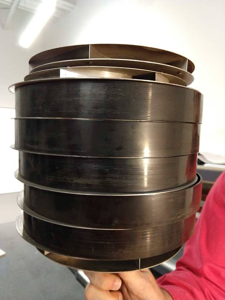
Here are some photos. I'm not sure they clarify things much...
|
This is the stack of 6 stages. The black ring has been removed from the top stage showing
the rotor vanes above the stator vanes.
|

|
Here's a closeup showing the vanes:
|
|
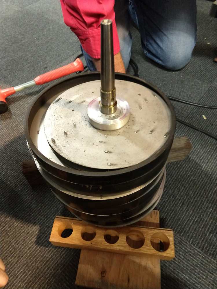
And here's a top view:
|
|
from Michael Marineau - Oct 30, 2019 11:09 pm
|
The bottom in that photo is also a stage (w/ black ring removed) so there are 7 total.
Hopefully all is well after we install the new bearing next week. If not it was suggested that we would
be able to take a pump from storage but it turns out the German vacuum pumps are completely different
and aren't even documented in the any of the 729 parts lists that I found. Are any of the 729s in storage German?
I've ordered a new sealed and permanently lubricated bearing which will hopefully not eat any aluminum
shavings that might still be hiding in the pump.
|
from Robert Garner - Oct 31, 2019 8:50 am
|
Marc, Michael,
Nice work!
The 729’s vacuum pump is an interesting contraption. (There must be a patent?)
I hadn’t fully appreciated Iggy’s detailed list of assembly and disassembly steps:
http://ibm-1401.info/IBM729-VacuumPump.html#Operation
> Are any of the 729s in storage German?
We have two donor DE 729s (50-Hz) in Yosemite.
The DE 1401 came with 2 Model V’s, 1 Model IV, and 2 Model IIs.
http://ibm-1401.info/1401GuidePosterV9.html
(We could have attached a 4th 729 to the DE 1401 but it would block the Liebert room door.)
The CT 1401 came with six 729s, so we have eleven 729s total, with four donor 729s in Yosemite.
- Robert
p.s. The DE 1401 came with five 729s and the CT 1401 with six.
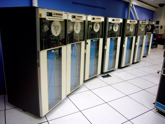
Group photo of the six CT 729s plus one DE 729 (taken May 2008):
|
|
|
from Ignacio Menendez - Oct 31, 2019 7:03 am
After thinking and remember my previous trauma with that pump, there were at least 3 stumbling blocks
that had us baffled (pardon the pun)
- when you have everything assembled, if the 3 a/c phases are not right, the pump still puts out air
from the exhaust port (no, it does not suck air from there), but very little air flow...
when correct, the exhaust port puts out lots of air.
- on the a/c power bus, that runs amid the drive, where all the motors are plugged, some
of the phases are not the same, so, if you plug it where it was originally, it should be OK,
but on some of the other receptacles it will not be OK.
- When you get all done putting it together, the parts will not all fit, until you go to the
other end, and remove and re-install that end’s bearing. I think this last one was figured
out by Ron Crane, May he Rest In Peace.
I think that I put all that in my notes (I hope).
------------------------------------------------
and from his the next e-mail Oct 31, 2019 8:54 am
Always one more thing, orientation of the pump in the 729 frame is critical, so the vacuum hose
fits properly and matches the vacuum receptacle in the drive.
------------------------------------------------
and from his the next e-mail Oct 31, 2019 9:56 am
Robert, as far as I remember, this particular vacuum pump is the only one of its kind, amongst all in CHM and warehouses.
|
from Michael Marineau - Oct 31, 2019 10:03 am
|
It is at least one of three, the three DE tapes all have the same model of vacuum pump.
|
from Ignacio Menendez - Oct 31, 2019 10:42 am
|
One more get you...
There are scribed marks (read screw driver scratches) on the outside of the middle and the two end sections....
This ensures that you can get the proper rotation orientation of the assembled pump into the 729,
the vacuum end points down to the connecting hose, and the air flow output comes from the top.
|
|