return to main 1401 Restoration Page
Microcoded 1401 from TTL ??
Purpose - Record a thread of e-mails - oldest first (on top) - not all e-nails in the thread are listed
- from David Troendle < david AT troendle DOT org > Microcoded 1401 - March 25, 2021 at 9:09:51 AM PDT
- from Robert Garner to a group - March 27, 2021 at 2:10 PM
- from Carl Claunch to a group - March 27, 2021 at 3:11 PM
- from Ken Shirriff to a group - March 27, 2021 at 6:55 PM
- from Ken Shirriff answering register question from David Troendle - March 27, 2021 at 8:30 PM
- from Robert Garner back to David Troendle - March 27, 2021 at 10:39 PM
- from David Troendle to a smaller group - March 28, 2021 at 11:00 AM
- from Carl Claunch to ??? - March 29, 2021 at 12:11 AM
Information about the 1401 team members maybe found in Team Bios
from David Troendle < david AT troendle DOT org > Microcoded 1401 - March 25, 2021 at 9:09:51 AM PDT
|
To: Robert Garner
Hi,
My first job as a student worker in college was as a 1401 programmer. I came to deeply admire its
amazing architecture, which accomplished so much with so little. When it came time to upgrade,
I very much missed it. Since then I have always wanted to own one, but the responsibilities of
raising a family and a career always came first. I retired in 2011 and went back to school in
2013, eventually getting my Ph.D. in 2018. Since then I have taught and mentored students at
Ole Miss as a volunteer in the
Heterogeneous Systems Research Lab.
A while back a friend called my attention to your work on the 1401 at CHM. That rekindled my
interest in the 1401. As part of my course work in architecture, I picked up microcoding skills,
and built a lab at my house capable of realizing my efforts. Eventually, my ability to do it
and my fondness for the 1401 resulted in my taking on a microcoded 1401 project.
My strategy is to construct a simulator in C++ structured to reveal and ease correct microcode
implementation. My biggest challenge will be correctly implementing the details missing in the
surviving manuals. Here are two examples I have discovered so far:
- The documentation is silent on where instruction fetch places a d-modifier. I suspect
it is left in the A-Reg based on my feel for the IF cycles.
- The 'Skip and Blank Tape" documentation in A24-3069-2 p. F-4 is missing the register
contents after execution. Again, that is fairly easily inferred from other similar instructions.
Eventually, this can all be validated by the hardware diagnostics program, which seems to have survived.
This gets me to the point of my email. From time to time I could benefit from some help
validating my guesses on fuzzy or undocumented details. I would only ask for help after
doing reasonable and appropriate research on my own. Also, I would appreciate feedback
on design decisions.
I plan on an initial build of 5 identical systems. In return, I would, up to 3,
give a system to those who have helped. I will keep one for myself, and donate one to the
1401 exhibit at CHM. I am open to adding interfaces to real devices such as the 1402, 1403,
and 729 as follow-on projects.
If I were you, I would be pretty skeptical at this point and have several "how you plan to"
questions, and would be pretty unwilling to go any further before getting reasonable answers.
So, I am willing to take on any questions you may have. It is pretty easy to anticipate
some obvious ones:
- Are you crazy?: No, but very obsessive. It helps.
- What will the system look like?: My current plan is a series of up to 8, 8.5" x 11"
boards on a 9" X 11" backplane, with each board being a 4-layers (Vcc and ground on the inner
layers). Three slots are dedicated: Front panel, micro-sequencer, and interface.
- How do you plan on doing I/O?: I/O would be handled via a Raspberry Pi mounted to the
interface board. Access to the Pi would be via wi-fi and
NOMACHINE remote desktop sharing to a
GUI application. Simulated devices would not implement any media-related errors. Tapes would
appear as arbitrarily long and rewind or backspace instantly. I have not thought through the
RAMAC details yet, but will probably implement as a 1311.
- What will the front panel look like?: My personal nostalgia is a strong driving force.
It will be as close to the original as I can make it. (But my mechanical skills are not very good.)
The board will have white silk screening on a black background. The front panel resides in the
first slot on the backplane. The look and feel of the board will be scaled down to those dimensions.
Bits would be implemented with two-color LEDs -- white for normal and red for error. The register
push buttons would be implemented with a push button and yellow LED instead of the illuminated push
buttons. Only the front panel with the switch flap closed would be rendered. The switches would
be via the GUI interface running on the Pi. One of the last things I would do is shadow the front
panel in the GUI. I feel the lights on the front panel are part of the charm of the 1401. So, I
would like a physical front panel.
- What do you anticipate the clock speed to be?: I expect 5MHz. I plan on implementing as
a Mealy FSM with a simple two-phase clock with 100ns for each phase. During one phase the next
state is computed from the current state, and during the other phase, the register transfers
occur. All parts can complete their work in well under 100ns. (E.G. the microcode EPROMs are 50ns parts.)
- Do you plan to sell these?: No. It would be easier selling used Toyotas to the Ford
or GM board of directors than selling these. I will place everything in the public domain. Once
I have the simulator substantially working, and am sure I can author the microcode, I will create
an evolving repository that contains the current versions of all the necessary components: Full
simulator source, KiCad files, PCB Gerber files, the source for the microcode compiler, and microcode
for all EPROMs. I plan on using commonly available 74HCxx 74LSxx parts. The only exception is the
initial version will use 27C160 1MBx16 EPROMs because I am not sure how big the microcode will be.
Once I know, I will redo using EPROMs of appropriate speed and size. I am open to an FPGA
implementation, but a TTL implementation is closer to an actual machine.
- Have you worked on other projects of similar size?: Yep, lots. One of the best examples
is I lead the technical team that installed the PeopleSoft Financial, HR, and Student modules at
LSU Health Sciences Center (9 public hospitals and 2 academic campuses) on time and on budget.
There were others such as Y2K and Katrina recovery. (We purchased new hardware (150 plus servers),
relocated to a site in Baton Rouge, and restored all systems at the new site in 2 very long weeks.
We did not miss a payroll nor miss a vendor payment.)
- Is all this worth it?: No, not really. You have to have a deep fondness for the 1401
to make it worthwhile. I suspect that universe is pretty much the CHM 1401 team and a handful
of 1401 enthusiasts. It is my hope you see it as I do, and that is why I reached out to you.
Well, I already taken up enough of your time, and won't impose further unless you want more
details. Feel free to ask questions.
David
|
from Robert Garner - to a group - March 27, 2021 at 2:10 PM
|
Folks,
Yesterday I received this interesting proposal from an "obsessed" 1401 aficionado who wants
to recreate a working 1401 CPU via TTL chips and microcode, along with a realistic front panel.
Your thoughts?
Then I can assemble a reply.
And are any of you open to assisting him, as he is requesting?
While I don't want to discourage him (he didn't mention any hardware background),
his outlined approach wouldn't be easy - although it would be educational! :)
Cheers,
- Robert
p.s. I'm not sure where he resides (I assume not in the Bay Area, as I suspect he would have visited us?)
|
from Carl Claunch to a group - March 27, 2021 at 3:11 PM
|
Hi Robert et alia
I would be delighted to help him. This type of quixotic and sizable project
is something I strongly support.
Please feel free to pass along my email address and name to David. Judging
from his volunteer efforts at Ole Miss, he is likely based in Mississippi.
Carl
|
from Ken Shirriff to a group - March 27, 2021 at 6:55 PM
|
I would also be delighted to help. It seems to me like two projects: one to build a TTL processor
and a second to implement the 1401 in microcode on top.
Ken
|
from Ken Shirriff answering register question from David Troendle - March 27, 2021 at 8:30 PM
|
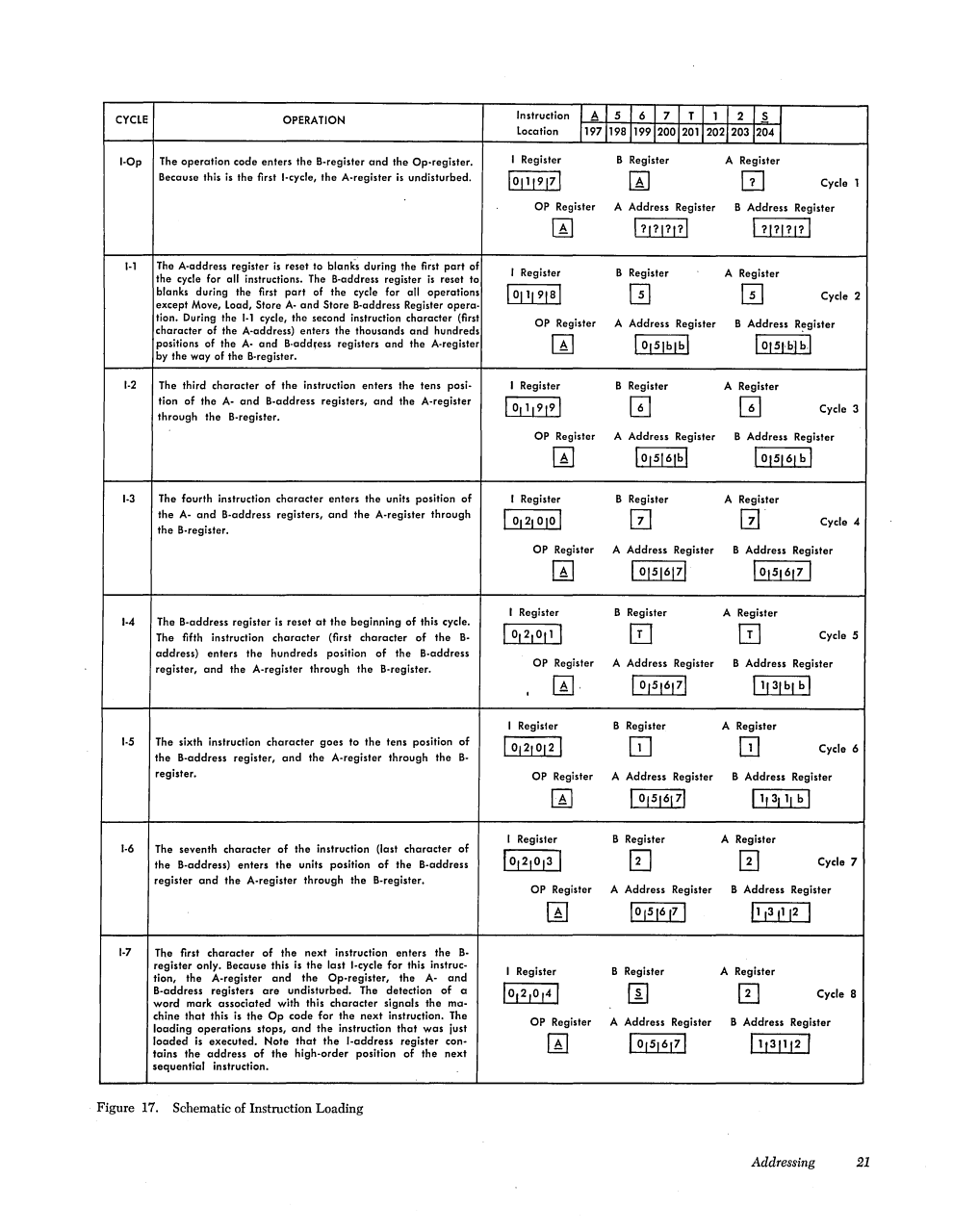
According to the 1401 reference manual, during instruction loading the characters all
go into the A register through the B register. The exception is the first character of
the next instruction (i.e. with the word mark). This character enters the B register
only, leaving the other registers undisturbed.
Ken
|
from Robert Garner back to David Troendle - March 27, 2021 at 10:39 PM
|
David,
Thanks for contacting us - you've reached the world's huddled experts on the 1401
and we're willing to assist! :))
I forwarded your email around the 1401 team, and several responded that they will
be delighted to assist you in your (harrowing :) hardware/firmware adventure. :)
So far, that includes Carl Claunch, Ken Shirriff, and Mike Albaugh (cc'd).
I've also cc'd our Van Synder, an expert on emulating & programming the 1401
(guru for all odd ISA questions);
and Ron Mak, who developed our 1401 software simulator environment (ROPE,
http://ibm-1401.info/1401SoftwDevel.html )
You can find their bios on our 1401 site:
http://ibm-1401.info/TeamBios.html
(Ken also hosts the remarkable electronics/computer restoration/reverse-engineering blog:
http://www.righto.com/
Don't worry, your craziness/obsessiveness is no worse than many of ours. :))
Best regards,
- Robert
|
from David Troendle to a smaller group - March 28, 2021 at 11:00 AM
|
To All,
Robert, thanks so much for forwarding my email to those with the expertise. To those who
expressed interest in helping, thanks for your kind offers of expertise and time.
Carl has already responded.
I will acknowledge the help of the team in my work product. I will try to expand
the number of systems to gift all who help a system. I hope my parts inventory can handle it.
Here is my current status.
- I have done a prototype backplane, on which I am testing the DC and AC
characteristics with a scope, signal generator, and programmable electronic load.
I want to ensure I get stable DC power distribution and AC signals that Schottky bus
transceivers can handle at 10Mhz. If I see concerns, I plan to ask a friend in
the EE department for advice.
- I am making slow progress on emulation. I all completed and unit tested
all branch instructions inclding their chained variants.
- I am just starting the additive instructions. That will take several days.
- I will do move/load instructions after the add instructions.
My first set of questions will be in my response to Carl.
Thanks to all again.
David
|
from Carl Claunch to ??? - March 29, 2021 at 12:11 AM
|
> FYI on the state of discussions. I had answered a set of detailed questions for him earlier.
I'm not going to try to get all the attributions right...
> Here is a summary of my thinking:
>        - Use the programming manuals to get a big picture of how each instruction works.
Mostly this will be refreshing 50-year-old knowledge.
>        - Use the ILDs to get the execution details.
>        - Do the micro-code on an emulator.
>        - Validate results against ROPE.
>        - Seek help if I can't figure out why validation fails.
Just a note: when I was working with the folks in Starkville on that 32-bit CPU, each of us
had written emulations based on the spec. Then we would send test-snippets to each other to
run. Any difference in the result (time-stamped trace of externally visible signals) would
be tracked down to either a bug in the test, a bug in one (or more) of the emulators, or
an ambiguity in the spec, with different people having different interpretations. This was
very helpful, but also taught us a couple lessons:
-
You need to do "unusual" (or non-sensical) things in the tests. Many times the "validation"
folks only test for what they think will happen. e.g. a 4-bit BCD adder would be tested for
the 20 expected digit pairs, any _hopefully_ with and without carry in.
Checking for behavior with 'un-digits" might be ignored. One startup I worked for may have
been driven over the edge by the failure to even check what result an "impossible" malformed
packet would have.
- Try not to "think like a programmer" so much. Our CPU first silicon had two bugs
that boiled down to the author of the HDL wearing their programmer hat to the extent of
forgetting to exhaustively say what each bit of state was changed in one case, and glossing
over the niceties of bypass in the pipeline. Both these were "fixed" well enough to begin
live development by not letting the compiler know about the problematic instruction variants.
I felt a bit better about the second one because National Semiconductor had a similar
problem on the early revs of their 16032.
> - Repeat for each instruction.
And for multi-instruction sequences (e.g. check that chaining works, and that the 16K "wrap"
triggers when it should, on the 1401)
> I think this is a more direct path to a working machine.
Totally endorse using (RAM based) emulation, over "Burn EPROM and pray". I had to do a fair
bit of that in the 1970s, and would not want to go back. Worse was "burn fuse based PROM,
with a programmer seemingly designed to encourage "DOH!" moments.
> The emulator approach could also be used for other architectures.
Yes, although there is always what Gerald Weinberg called "Fischer's Fundamental Theorem" as
applied to computing: The better adapted an organism, or system, to its environment, the harder
to adapt to changes in environment"
> Nostalgia is at play here. I was planning on a system similar to the two systems I used in the
60's: To the base 1401/1402/1403, I plan on these additions: RAMAC: 1311 with direct seek; Tape:
6 729s; Special features: 16K, advanced programming, indexing, overlapped I/O, multiply/divide,
high-low-equal compare. I have not thought through everything yet.
I'd advocate for at least enough of the Serial-IO (kitchen sink) adapter to provide an
interactive terminal. A full-blown 1407 with all the debug stuff might be overkill, but you
may very well want to play Colossal Cave, or checkers...
> Another question - will you implement the arithmetic in qui-binary and map between it and
BCD, as the real 1401 does, or do the math directly in BCD?
>
> I was not aware the 1401 was internally qui-binary until I saw the ILDs yesterday.
(I guess the 650 guys had some say in the 1401 design.)
The 650 was bi-quinary, with the single top bit weight of 5 and the lower three bits counting
0,1,2,3,4 (ignoring the actual 2 of 7 coding) while the 1401 is qui-binary, with three bits
counting 0,2,4,6,8 and one adding 1.
> I have not completely thought this through, but my current thinking is that the hardware
completely hides the qui-binary, and only the BCD shows.
At the very least, 1401 arithmetic has to treat "all bits zero" as zero, while producing
(8,2) for a zero result.
> It does not really matter all that much as I plan to use an EPROM for the ALU.
I can program either way. Right now, I see direct BCD arithmetic as the simplest,
fastest approach. The BCD to qui-binary conversions would require micro-instruction cycles
and slow down things with no benefit that I can see. Set me straight if I am missing something.
There may be similar issues involved in the collating sequence used by the Hi-lo-equal compare.
...
-Mike
|