"1403 info (long)"
e-mail from Ken Shirriff, Sept 5, 2018After studying today's oscilloscope traces, I've noticed that there's no evidence the PLC plane on the core memory is getting cleared. The blank spot that we thought was the core getting cleared during scan 49 is really just the gap between sub-scans while the chain lines up. So we have two possibilities: a) we're computing the inhibit signal wrong and writing 1's to core (the theory we left with today), or b) the core is never getting cleared to 0 in the first place (my new additional theory). I don't think anything we looked at today would help us distinguish between these two theories, so we should check this next time.
The remainder is my (long) summary of today's printer debugging, mostly to help me keep track of what we looked at.
The problem is the DE machine hits a printer check when it prints a character; printing a line of blanks is okay.
Last week we traced it to the Print Line Complete check, which among other things checks that you don't try to print
two characters in one spot. (The 1401
Data Processing System Instruction Logic document describes the printer checks in detail (page 98).)
When the computer decides to print a character (i.e. a Print Compare is true), it sets a 1 in that position in the
printer buffer's Print Line Complete buffer. It also sets a 1 for a blank or unprintable character. At the end of the line
(scan 49) it verifies that all positions hold a 1, but that's not the problem we have. Our problem is that when it
decided to print a character, it verifies that there is not already a 1 bit there, and this test fails.
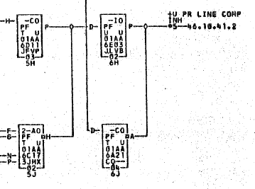
The relevant circuit is in 36.37.11.2:
D is -PR LINE COMP LATCH (i.e. the value stored in the PLC core plane)
E is -PR COMPARE (i.e. if we want to print this character now)
The gate is two negative-input ANDs, OR'd together. In other words, if PR LINE COMP LATCH is true/low
(there's already a character for this position) and PR COMPARE is true/low, then PLC CHECK is triggered.
We verified with the oscilloscope that this is what happens: D (cyan) and E (pink) both go low, triggering C
(PLC check, blue) at the right time to trigger the error (yellow). Note that C (blue) pulses a lot,
but it is gated, so it's only the "extra" pulse in the middle that causes an error. So far, this is confirming last week's investigation.
The next question is who's to blame. Is it D (cyan) - are we getting a bad value from the core memory,
indicating that the character has been printed already or is blank? Or is it E (pink), the signal indicating that we want to print the character? Is the Print Compare logic messing up?
We did various experiments and found that the Print Compare logic looks right. If we have one printable character,
it turns on once. If we have two printable characters, it turns on twice. And it's printing the right character.
So this signal seems okay. We also looked at the non-printable character signal (that sets the core bit at the start) and it seemed correct.
It looked like D (the signal from core) was bad, so either we were writing the wrong value to core,
or we were reading the value back incorrectly. Various tests made us suspicious of the write, so we looked at the PR LINE COMP INH signal, the signal to write to the PR LINE COMP core plane
Here's the relevant circuitry from ILD 77 to generate PR LINE COMP INH, i.e. the inhibit signal to write to the PR LINE COMP plane.
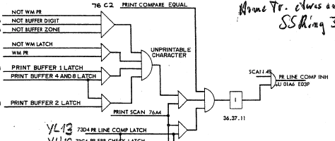
Starting at the right, the round OR gate generates PR LINE COMP INH; it is 1 (clear the cores) in SCAN 49
(end of the line). It is 0 (set the core) for PRINT COMPARE EQUAL (i.e. we're printing a character here), an unprintable character, or PR LINE COMP LATCH (i.e. the core was 1 before so keep it set).
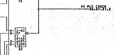
In ALD 36.37.11.2, this circuitry is below. The right OR gate above is a wired-or. The middle OR gate is a combination
of the OR inside the 3JMX and a wired-or. In the lower left, F is -PRINT SCAN, G is the - non-printable character signal, N is -PR LINE COMP LATCH (from core), and P is -PR SCAN CKT 1.
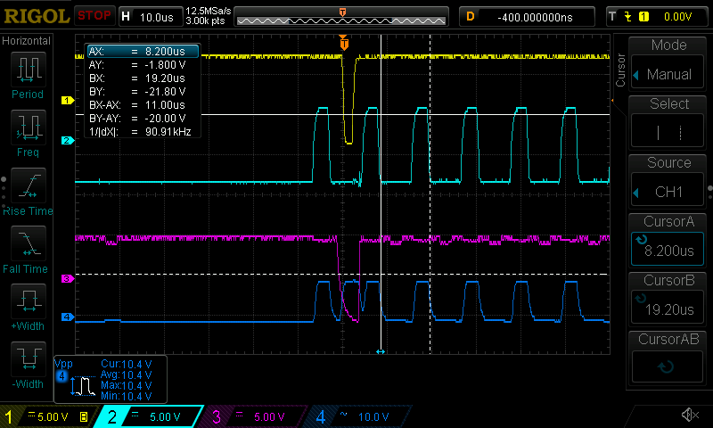
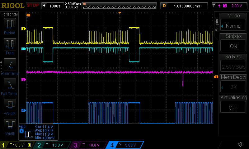
Printing a single character means that 131 out of 132 PLC bits will start out as 1, and one should start out as 0. This was kind of a needle in a haystack, so we tried a line with 60 blanks and 72 characters. The trace below shows PR LINE COMP INH yellow, output H in the lower left (the output from the 3-input AND gate) cyan, print compare pink, and not printable character blue. The blue signal has a long low part (60 blanks), a long spiky part (72 characters), and a high part (end of line, gap while chain lines up for next subscan. That looks good. The pink shows a spike when a character is printed, which looks good. The yellow and cyan signals look weird and spiky, suggesting we're writing bad stuff to core. If a core is set to 1 erroneously, this would trigger the fault we see when we try to print that column.
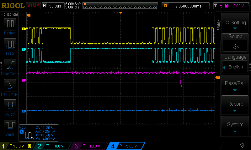
We swapped a few of the cards in this circuit, but with no effect. We then moved to the CT machine to compare the signals on a working machine (below). Note that the yellow and cyan signals are no longer weird and spiky, but show real signals. In addition, you can see the inhibit signal setting the core when the character is printed (the pink spike). The blue signal (not printable character) is missing entirely which is strange; I suspect we just probed the wrong signal.
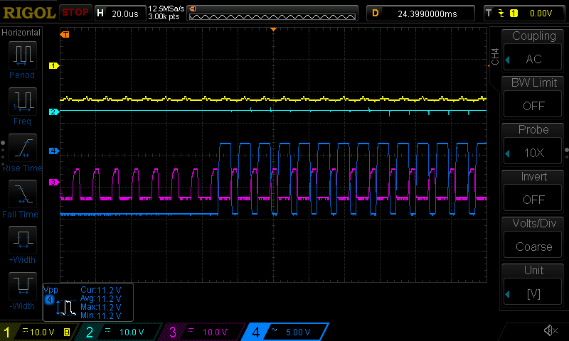
This confirms that the PR LINE COMP INH signal is bad on the DE machine, compared to the CT machine. But why? Marc's theory is that the signals going into the 3-input AND gate are out of phase, so instead of getting good signals, we just get spikes at the transitions. This matches what we measured below. The trace below shows the inhibit signals (yellow, cyan) as well as N (-PR LINE COMP LATCH from core, pink), and G ( - non-printable character signal, blue) Note that the pink and blue are out of phase as suspected. This keeps one of the -AND gates always active (F and P are usually low (active)) so the cyan signal (H) is always stuck high (0V), except for little glitches. This causes 1's to be written to the core, triggering the problem. But the out-of-phase signals could simply be because we're reading 1 from the core plane. Note that the pink signal doesn't change between the blanks (left) and the characters (right).
We thought maybe the latch of the data from core (pink, PR LINE COMP LATCH) had bad timing, so we did a quick comparison of the PR LINE COMP LATCH output with the HAMMER LATCH output, but didn't see any obvious timing differences.
It seems like we've gone in circles: we see bad data coming from the PR LINE COMP core plane, and we write bad data back to the core plane. It's unclear which is the cause and which is the effect.
That's where we ended today. We hope that another comparison of timings with the CT machine next week will reveal where things are going wrong.
P.S. Some important timings for interpreting the printer traces from the
manual:
A hammer lines up with the chain (i.e. an option to print) every 11.1 microseconds. (These are the individual pulses in the traces.)
A sub-scan is 555 microseconds. (This is a block of pulses in the traces.) This consists of 488.4 microseconds of print options, and 66.6 microseconds lining up for the next subscan.
Three subscans make up a scan: 1665 microseconds.
48 scans make up a print line, with a 49th scan to check for errors. Including the line feed, a print line is about 80 milliseconds.
Ken
On Wed, Aug 29, 2018 at 5:58 PM Ken Shirriff
Here are my notes and thoughts on the 1403 debugging today. At the end of this, I reach pretty much the same conclusion as Marc's text, but hopefully the additional context will help. (Also, it ensures that I'll have this information when I need it a year from now.)
Testing
First: some interesting observations. Blank lines print fine (no errors). Printing any character in any column (based on small sample) causes the character to print correctly, but an error is reported.
Relevant ALDs are 36.37.11.2 (generates PLC CHECK) and 36.37.21.2 (print check latch).
Testing showed the latch operating correctly. It was triggered (low output = error) when inputs F and G went high simultaneously. (F is the error signal and G is PR CK SAMPLE, essentially the clock). Most of the time, F and G go high alternately (no error), but by triggering the oscilloscope on H (latch output), we could catch the rare point at which both go high simultaneously, indicating the problem. (We had a 2-channel oscilloscope, but could trigger on a third signal.) Error signal F is inconveniently the wired-OR of three different signals, but we used two tricks to untangle this. By looking at expansion pin G or P on the CJWF card, we could see the state before the OR. Also, by using an extender card, we could disconnect the output so it wasn't part of the wired-OR.
From this, we determined that the problem was not the CJWF gates on 36.37.21.2 comparing HAMMER FIRE and EQUAL CHECK (testing if a hammer failed to fire or fired incorrectly, as explained below). Instead, the problem was the PLC check on 36.37.11.2. In particular, not E07 but D05 input E. (This is in ILD page 77 D3.)
Background
The 1403 printer mechanism is a bit tricky. I wrote about it
here. The relevant part is the chain has 48 characters. As the chain moves, a hammer and a type element line up every 11.1 microseconds. This is a "print option", where the 1401 has the option of printing a character. The 1401 reads the character from memory (print buffer) corresponding to the hammer, compares it with the type element under the hammer (the "print compare", and either fires the hammer or not. Note that the printer doesn't print a line at a time, but each hammer fires at a separate time.
The alignment between hammers and the type chain is very tricky. It's essentially a vernier, so a tiny movement of the chain lines up a different hammer. Every third hammer lines up in sequence. A "subscan" is the time in which 1/3 of the hammers have had an option to print. Three subscans make up one print scan, which means all hammers have had a chance to print one character. Since there are 48 characters, it takes 48 print scans to print a line. Then the 49th print scan is used to perform checks.
Some background on the core memory. In addition to the normal core plans (8/4/2/1/A/B/C/WM), there are 6 I/O core planes. These use the same addressing as the regular planes, but are accessed separately. The RD1-PRT and RD2-PCH planes have cores wired directly to the two card reader stations, the printer hammers, and the punch magnets. By "wired directly", I mean there are 132 wires from the printer hammers and each wire is wound around a core. Not just the normal grid, but wires directly to individual cores. There are also four planes that have the normal grid wiring but are used for I/O: XU 11, YU 12, YL 13, XL 14. For information on the core planes, see
my article and the diagram from ALD 42.41.11.2.
Printing uses plane 10 (hammer-fire), plane XU11 (print-compare), plane YU12 (error storage), and plane XL13 (print-line-complete). They have addresses 201 through 322 (same as regular print addresses). (The U/L names make more sense when these planes are used by the card reader for hole counting.)
In the ALDs, these planes are referenced as HAMMER FIRE LATCH, EQUAL CHECK LATCH, PR ERROR LATCH, and PR LINE COMP LATCH.
Details on printer checks
The 1401
Data Processing System Instruction Logic document describes the printer checks in detail (page 98). There are a bunch of checks, but the relevant ones are:
Hammer Fire - Print-Compare Check: This checks if a) a hammer failed to fire when it should, or b) a hammer fired when it should not.
The idea is each print option, the hammer fire core is reset to 1. If the hammer fires, the back-pulse goes through the core and sets it to 0.
Meanwhile, the print-compare core is reset to 0 if there is no print compare (i.e. the wrong character is under the hammer so nothing is printed). It is set to 1 if there is a print compare (i.e. the character under the hammer should be printed).
Then, each print scan checks these two cores (address by address as it goes through the scan) to make sure everything worked in the previous scan. If they have the same value, it raises an error. I.e. both 1 indicates the hammer failed to fire, and both 0 indicates the hammer fired by mistake.
This test is performed by the CJWF cards on 36.37.21.1. From the oscilloscope measurements, this test is not a problem.
The next test is Print Line Complete. This makes sure that each of the 132 positions tried to print something during the line. Each core is set if it gets a print compare, or if it is blank or unprintable. In scan 49, all the cores are tested to make sure they are set. If a core is 0, something went wrong since the 1401 never tried to print the character. Note that this test has nothing to do with hammers. This test is done by the CJWV on 36.37.11.2.
The error storage cores are checked by the 4JMX on 36.37.11.2 that feeds into PLC CHECK. (I would consider this error check unrelated to PLC but whatever.)
The third thing fed into PLC CHECK is the PR LINE COMP LATCH check also using the 4JMX. I believe this detects if a character triggers print-compare twice (i.e. an attempt to fire a hammer twice; PR COMPARE is set and the LINE COMP core is also set). From the oscilloscope measurements, this appears to be where the problem is happening. Something could be going wrong with the print compare circuitry (ILD 76, ALD 36.33.21.2) or the read-out of the print-line-complete core planes. A problem with the print compare circuitry would have to be fairly subtle, since the right characters did get printed. If the core plane sense amp were stuck on, for instance, I think that would explain the problem. Or simplest would be a problem with the 4JMX card that generates the PLC CHECK signal.
Ken