On Saturday, 10/2, Bill Flora & I compared these schematics against the Deutsche 1402 (DE 1402) and the Visible Storage 1402 (VS 1402). It was nice having them sitting side-by-side!
On first inspection, the DE 1402 wiring appears to match these schematics, with the following six caveats:
-
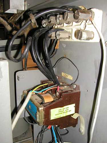
The DE 1402's original remoteControl+manual "Circuit Breaker I"
was replaced with a combined 3-phase line filter + remoteControl
"Contactor I," while eliminating "Circuit Breaker II" for the 729 tape
drives, according to the schematic below.
(I wonder if there are circuit breakers in the 729's?)
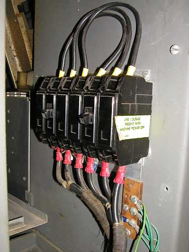
The contactor's remote control logically would be from the on/off button on the 1401 main control panel. See pics below of both 1402 AC power input setups. The AC low-pass line filter must have been a field mod for noisy power environments. It's certainly not in the VS 1402. (The VS 1402 circuit breakers seem to be manual on/off only - I don't see their remote control connection.) - The DE 1402 schematics specify 10-gauge power lines. The
undersized, non-standard power cord that came with it seems to be something like
14 gauge (although I didn't measure it).
A 10-gauge wire is good for 33A (enclosed air space), so three, in-phase lines could safely carry 3*33A*220V = 22 kVA, more than adequate. 3-phase 14-gauge wiring would be marginal at 3*17A*220V = 11 kVA, esp. with power factors, etc..
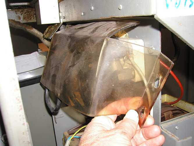
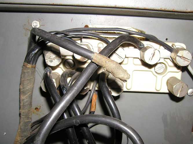
- A worrisome issue, as 1st noted by Don, is that the DE 1402's
ceramic AC wiring assembly is cracked at its upper left and upper right
corners, at both ends of the neutral return bus bar, causing the metal posts on
the strip to peel inward; and it's plastic cover is melted, most certainly
due to high temps.
The picture is below.(The VS 1402 does not have a neutral bus bar, as it is 4-wire Delta connected, without a return neutral.)
I've been postulating as to what may have caused this over heating. (The neutral bus bar metal strip itself was clearly oversized by design.
And they must have expected high currents there to, or else why the protective plastic cover? Perhaps the bus bar/ceramic may have been over heated by one or more of the neutral wires connecting to it?) Here are the possibilities I've come up with (most-to-least likely):
- One of the 3 phases in one (or more) motors is disconnected or
has a poor connection? This unbalances the 3-phases, resulting in the
other two, non-canceling return current phases flowing into the
neutral line.
- The neutral post screws came loose over time, causing overheating?
- A misbalance in the 3-phases, causing too much return current
on the neutral line? This might be the case if most of the power were
on one of the phases. (From the wiring schematics, I noticed that the
1403 DC power, 729 bulk, & 1401 blowers get their power from Phases B & C,
whereas Phase A supplies connector PWB-13/14 as "system power".
All the motors are all 3-phase.)
- The 3-phase, undersized, 14-gauge wire is resistive, forcing
additional current to return via the neutral?
- 3rd harmonics on the neutral due to non-linear supplies, causing overheating?
I'm not sure how to best approach figuring out the problem. In any case, I'll purchase a 50-500V "Megger" to test for wire-to-wire and wire-to-ground leakage faults. We'll test paths not only in the 1402, but also in the 1401 and 729's.
- One of the 3 phases in one (or more) motors is disconnected or
has a poor connection? This unbalances the 3-phases, resulting in the
other two, non-canceling return current phases flowing into the
neutral line.
- It was interesting to compare the VS 1402 to the DE 1402 power
cords. (We do not seem to have schematics for the VS1402 - I'd like to find
some.). The VS 1402 is a 3-phase, 4-wire Delta power connection (3 current
phases plus earth ground) with a large gauge wire (perhaps 8), and the DE 1402
is a 3-phase, 5-wire Wye connection (i.e., 3 current phases plus
neutral current return line and earth ground wires) with a little smaller 10-gauge
wire. (I've read Wye is/was favored in Europe and Delta is/was favored in
US.)
I do not think we can use the VS 1402's big, 4-wire delta cable, as we should not tie neutral and ground together at the 1402. That would unsafely place neutral return currents on the chassis of the entire system, and is not to code.
Jim Yee can get us a new 5-wire, 10-gauge cable for connection to the Elgar.
And we'll need the proper 5-wire Russellstoll receptacle/female plug.
(I would prefer a Russellstoll screw-on to a twist-type, given that the connector is situated out in the room where someone can easily bump it.)
Standard charts show 30A, 5-wire, 277Y/480V, which would handle our 220Y/380V config.
The Elgar output bus enclosure has a neutral wire inside it (i.e., it's 5-wire).
- The VS 1402 also has a hefty copper bar as an earth ground point,
and the DE 1402 had a poor, loose ground screw connection to the frame.
(Pictures in next msg.)
- We figured out what the large missing item that the fan cools in
the left front of the DE 1402 is: It's the +-3V @ 5A power supply for margin
checking.
(I wonder if it was packaged separately in another box, or is gone? Arnold?)
- Robert
Below are 3 scanned pages of the DE 1402 power wiring, which powers the entire 1401 system.
Here are the schematics:
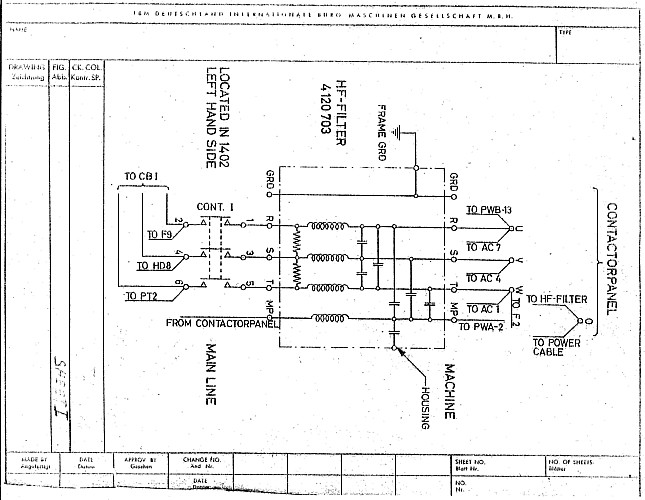
1402 Power Line Filter |
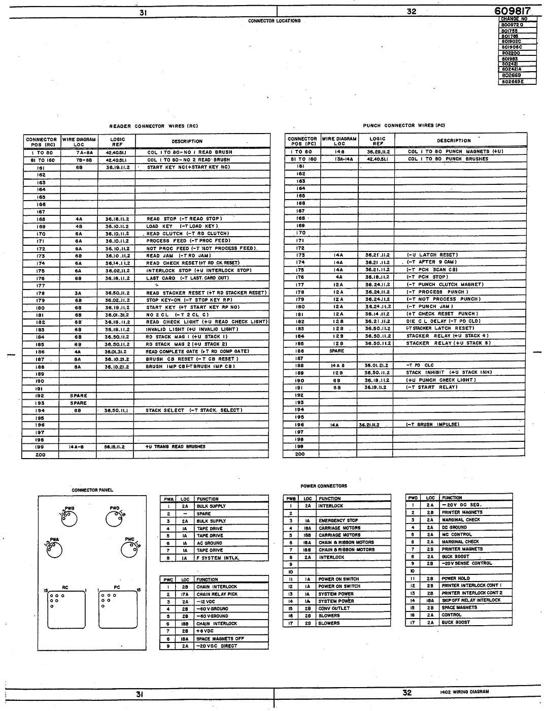
1402 Power Connections |
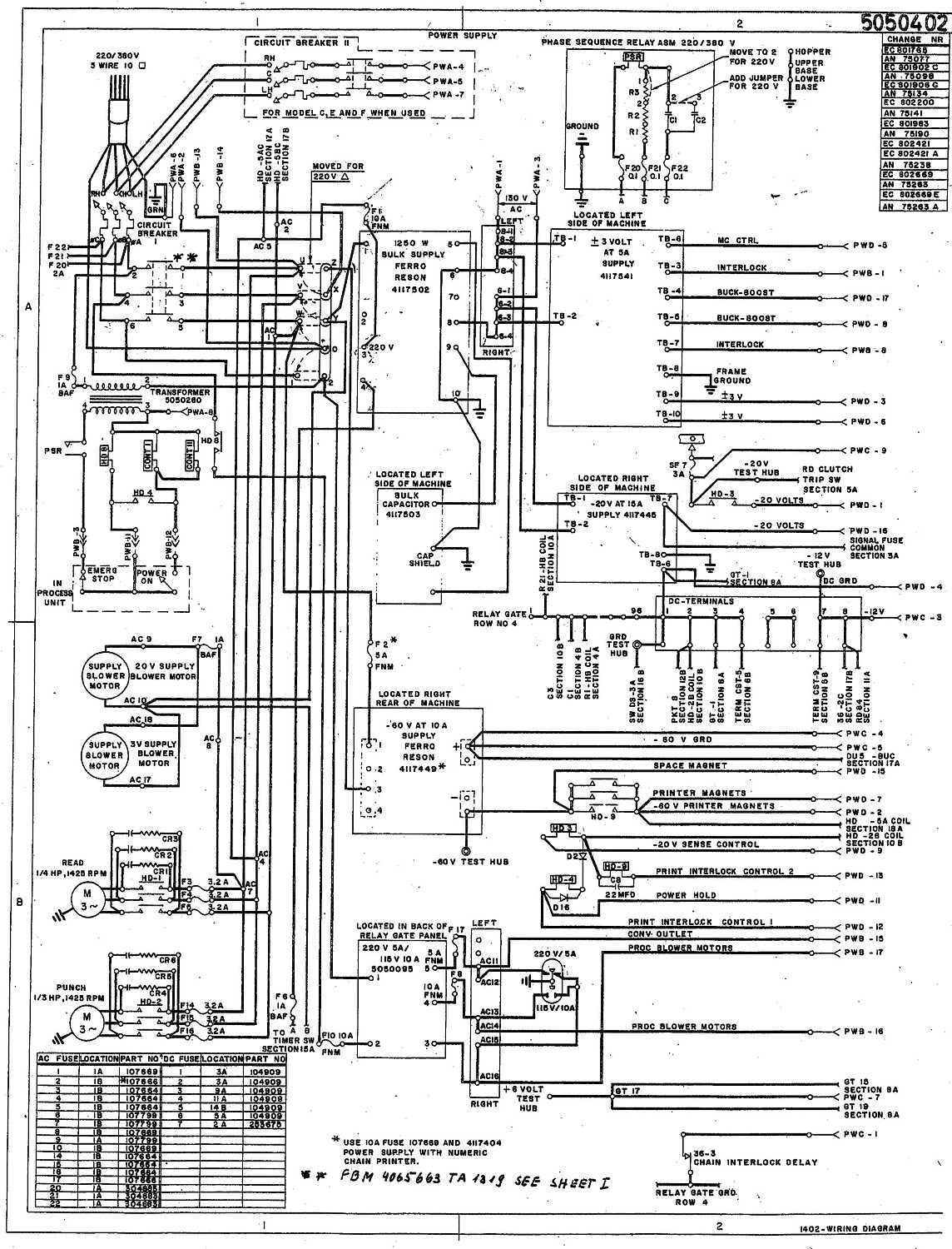
1402 Power Wiring |
| 1402NeutralCover | ||||||||||||||
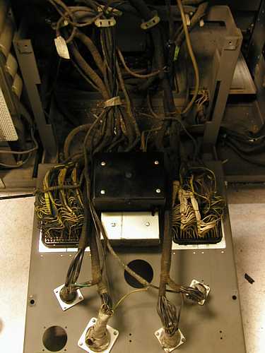
| DE1402ACWiring - Here the picture of the DE 1402's AC power input to
line filter block
and cracked ceramic block. The upper 5 posts are connected together as
the neutral return bar and the 3 lower left posts are the 3 phases.
(the right crack is hard to see because of bright flash. The left neutral
post is clearly bent inward from cracking). The undersized ~14-gauge white
neutral wire is on the right.
1402NeutralBar
| 
VS1402ACWiring -
| 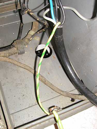
DE1402EarthGnd
| 
1402PwrCords
| 
VS1402ConnWiring
| 
DE1402ConnWiring
| 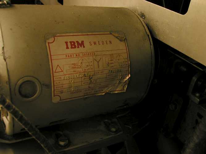
1402Motor
| |