Collected by Ed Thelen
Table of Contents
History
from Tom Gardner
|
I was poking around in tape history and picked up a few facts that you might want to add.
The first model was the 729 Model III announced as part of the 705 Model III circa September 1957
[Source: Datamation, Oct 1957] It was followed by the Model II and IV announced on
December 30, 1958 as part of the 7090 announcement;
they were then announced for the 1401 on October 5, 1959. [Source: IBM mainframe archives]
http://bitsavers.trailing-edge.com/pdf/ibm/magtape/729/223-6845_729_CEman_1959.pdf
As near as I can tell the III and the IV were the same machine except that the III
had tube I/O levels while the IV had transistor I/O levels. The II also had a transistor I/O.
[Source: The
CE Manual listed in yr article]. This leads me to conclude the II and IV were later
than the III since they were used on transistor based systems the first of which was the
609 shipped in Dec 1957 but didn’t use tape – the first IBM ones with tape might were the
7090 and the 1401 in 1959 which dates the 729 II and IV to 1959 (which is the date of the manual).
In other e-mails, Tom mentioned:
- Youtube video -
IBM Tape History - Session 1: Tape Media Part 1
- CHM catalog entry
IBM tape history - session 5: recovery of tapes damaged in Challenger disaster
which links to - .pdf - near bottom of page
|
from Robert Garner
|
Tom, Paul,
Another interesting aspect of this IBM magnetic tape/peripheral history (per 1401 market planner Shel Jacob's oral history) is that - in the couple of years before the 1401 announcement in 1959 - IBM market planning did not anticipate/envision what happened: that tape-based 1401s resulted in an era-shifting transition from storing data on unit-record punched cards to storing data on much denser magnetic tape. (Perhaps since IBM was so ensconced in the profits of making and selling punched cards. The 650/700-series folks had foreseen such a transition, but those systems were too expensive for most of the business market.) As an example, the 1401Ős first customer, Time-Life, exemplarily converted its entire subscriber database of 40 million punched cards onto just several hundred magnetic tapes. Similarly, nor did IBM marketing anticipate that 1401s would come to dominate the European market because of the high demand there for their reliable tape drives.
Per Chuck Branscomb's oral histories, because his boss, Bob Evans, ostensively wanted 1401s to be used as I/O spoolers for 7000-series systems, the 1401 design team, at the last possible moment, transplanted a 7040-based 729 tape controller into the 1401 (using different voltage logic levels and placed in the expected-to-be-optional 2 cubes on the right side.) Nevertheless, entirely unanticipated, over half of all 1401 installs became full-sized, four-cube, highly featured, tape-based systems. Since by 1965 half of all 28,000+ computers worldwide were 1400s, that market penetration represented a much larger business success that if 1401s had only been 7000-series I/O spoolers. The wide spread adoption of tape-based 1401s was entirely missed by IBM market planning.
In this Oct, 1961 IBM internal Poughkeepsie memo to Palmer (attached), Buchholz begins by noting that "Although the 1401 was originally conceived as a senior card accounting system, a major fraction of the 1401 sales are for tape data processing systems" and goes on to reflect on how an updated tape-based 702 may have achieved the same market success as the tape-based 1401 systems: "In retrospect therefore, it would seem that a 702 redesigned in 1401 technology would have been no more expensive than the 1401 and functionally equivalent." Of course, the challenge for IBM was that Poughkeepsie wasn't pursuing the low-end, unit-record-equipment-based business marketplace (and perhaps couldn't see that small businesses were pining for the space-saving advantages of magnetic-tape storage?)
pictures not included
Take care,
- Robert
p.s. A table of the "world's most popular processors", by year and approx. installed base, would be an informative addition to a computer history book? (Ditto for disk drives?)
I suppose it might be along the lines of:
UNIVAC - 50
IBM 650 - 1,000+
IBM 1400 family - 14,000+
IBM S/360 family - 50,000+ ?
DEC PDP-8 - 50,000+ ?
Intel 808x family (IBM PC) - 5,000,000?
MOS Tech 6500 family (Commodore) - 17,000,000 ?
? - ?
MIPS - ?
ARM series (in everything) - 10 billion?


> On Jul 3, 2020, at 6:55 AM, ed@ed-thelen.org wrote:
>
> > p.s. My theory as to (one of the reasons) why IBM dominated in Europe
 - even though Europe had a head start commercializing computers - was because
> of the reliability of its 727/729 tape drive storage peripherals.
>
> What a fascinating theory !!
>
> Background:
> I maintained GE 225 systems in the early 1960s
> and had way too much experience trying to keep Ampex tape drives
> (designed and made in the U.S.A.)
> working in business situations. - such as sorting large files -
> http://ed-thelen.org/EarlyGE-Computers.html#Ampex
>
> While trying to find pictures for the above tirade,
> I found this:
> http://ed-thelen.org/ICT-1301-Restoration.html
> ICT in England was using the same unsatisfactory Ampex tape drives.
>
> The General Electric Computer "Department"
> had a lot of trouble with peripherals imported from England !!
> http://ed-thelen.org/EarlyGE-Computers.html#crappyness>
> - card readers from Elliot,
> http://ed-thelen.org/EarlyGE-Computers.html#Elliott>
> - tape drives from Decca
> http://ed-thelen.org/EarlyGE-Computers.html#Decca>
>
> -Ed Thelen
|
General
|
There is a 729 tape manual at
http://bitsavers.trailing-edge.com/pdf/ibm/magtape/729/223-6845_729_CEman_1959.pdf
A24-3069-2 says that the 1401 can use the following
729 Magnetic Tape Units - II, IV, V, VI although the
729 - VI operates at 729 IV speeds only.
A24-3067-2 System Operation Reference Manual
A24-3144-2 Operator's Guide,
page 63 starts the "IBM 729 and IBM 7330 Magnetic Tape Units"
- as many as six tape units can be attached to the system
- All tape units in the system must be the same model, unless the tape-intermix
special feature is installed.
- all models of the IBM 729 and IBM 7330 have dual density.
- Density is controlled by a key (729) ... on the tape unit
Operating
Characteristics | 729II | 729IV | 729V*
Density - Low ->
(Characters per inch)
High-> | 200
or
556
| 200
or
556 | 200
556
or 800
| Tape Speed
(Inches per Second) | 75 | 112.5 | 75
| Interrecord Gap Size
(Inches) | 3/4 | 3/4 | 3/4
| Character Rate - Low Dens->
Characters per second)
High Dens-> | 15,000
or
41,667
| 22,500
or
62,500 | 15,000
41,667
or
60,000
| High-Speed Rewind
(Minutes) | 1.2 | .9 | 1.2
| Regular Rewind
(Inches per Second) | 75 | 112.5 | 75
| |
* Density and Character Rate affected by Tape Density Switch
- on 1401 Auxiliary Console.
|
- Characters are recorded on tape in binary-coded decimal (BCD) code,
the same code as used in core storage.
- An interrecord gap, followed by a special single-character record known as
a tape mark, is used to mark the end of a file of information.
- Reflective markers are placed on the tape, to mark the beginning
and the end of the usable portion of tape.
Photoelectric cells recognize load-point marker (where reading
or writing is to begin)
- or and end-of-reel marker (where the writing is to stop).
- The tape unit does not recognize the end-of-reel marker
when reading tape. Instead, the tape mark written on the
tape signals an end-of-reel condition.
- The markers are small pieces of transparent plastic with a thin film of aluminum on one side.
- Load-Point Marker - At least 10 feet of tape must be allowed between the beginning of the
real and the load-point marker - placed parallel to and not more than 1/32" from
the edge of the tape nearest the operator, then the reel is mounted.
- End-of-Reel Marker more than 14 feet from the end of the tape.
(ten feet of leader and enough tape to hold a record of 9600 characters
after the end-of-reel marker is sensed - away from the operator, when the
reel is mounted.
Tape Reels - 10.5" in diameter, holds 2400 feet of tape - (a 2400 foot reel can contain
about 13 million characters, assuming records 2,000 characters in length,
written at 556 characters per inch.)
Each reel is equipped with a file-protection ring to safeguard
data written on the tape. fits into the groove in the back (machine side) of the
reel - no ring - no write
Reel-Release Button - below the left-hand tape reel - It must be held
pressed to turn either tape reel by hand.
REEL DOOR - Interlock prevents any automatic
or key-controlled operation when this door is open.
This door should never be opened when the READY light is ON
or curing load, rewind, or unload operation.
With the door open during any of these operations,
the tape could become damaged.
"File Reel" is on the left, the "take-up" reel is on the right
The upper half of the Read/Write Head Assembly pivots
- up (open) when the UNLOAD is pressed
or after a REWIND TAPE AND UNLOAD program instruction
which also unloads the vacuum columns
and must be open before opening the reel door to make manual adjustments
- down (normal) after the LOAD REWIND key is pressed
which also loads the vacuum columns
The 720 uses a two-gap write/read head to enable on-line check while writing data.
There also seems to be erase head logic.
|
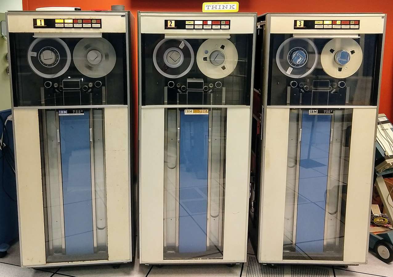
The serial numbers of our drives, and notes from Ken Sherriff
Here's a summary of the tape drives in the 1401 room (largely for my own reference):
DE tape drives
1: Serial 21944 B2
729 II, relay logic. Manual in lab.
2: Serial 34949 C4
729 V, NOR logic. No manual for this serial number.
3: Serial 34825 B4
729 V, NOR logic. No manual for this serial number, but manual for 34827.
(I don't know what the B2/C4/B4 in the serial number indicates. Maybe Iggy knows?)
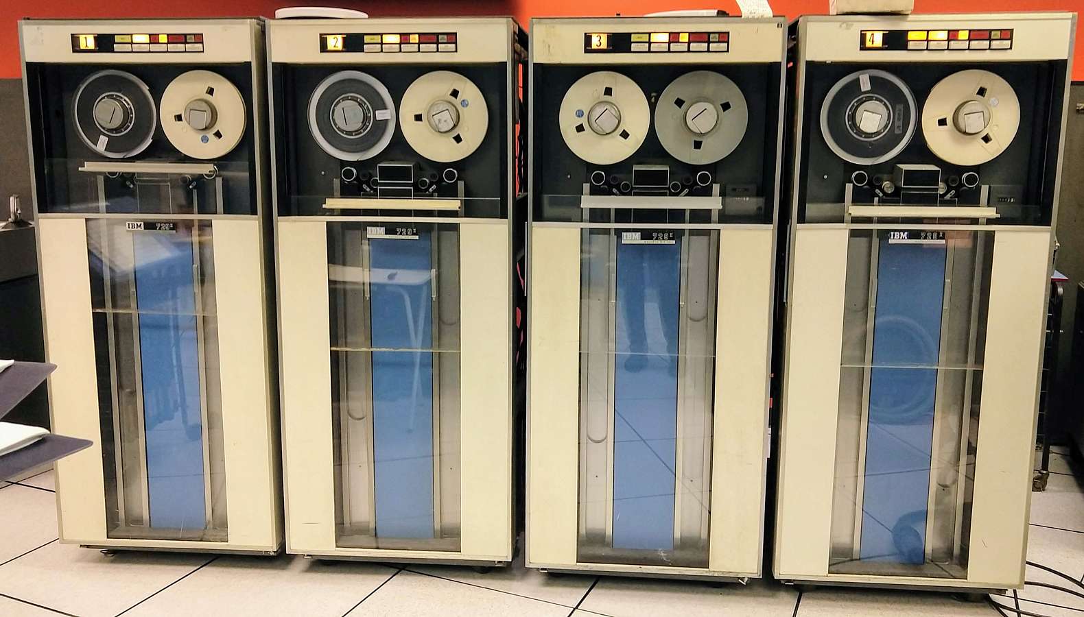
 CT tape drives
1: Serial 74895 S1
729 II, relay logic. Manual in lab.
2: Serial 71615 D1
729 II, relay logic. Manual in lab.
3: Serial 30230 H2
729 II, NOR logic. Manual in lab.
4: Serial75512 A2
729 II, relay logic. Manual in lab
CT tape drives
1: Serial 74895 S1
729 II, relay logic. Manual in lab.
2: Serial 71615 D1
729 II, relay logic. Manual in lab.
3: Serial 30230 H2
729 II, NOR logic. Manual in lab.
4: Serial75512 A2
729 II, relay logic. Manual in lab
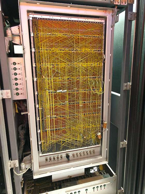
 Relay logic vs NOR logic
The relay logic drives and NOR (i.e. SMS) logic machines are entirely different internally,
so you need the right documentation.
Here's the back of a relay logic tape drive:
Relay logic vs NOR logic
The relay logic drives and NOR (i.e. SMS) logic machines are entirely different internally,
so you need the right documentation.
Here's the back of a relay logic tape drive:
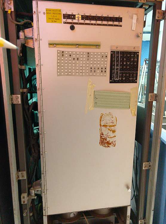 Here's the back of a NOR logic tape drive:
 The Model II and Model V drives are almost identical inside. The V supports 800 cpi writing
so the head is slightly different. The only visible difference I could find is
the Model V has YEU cards in K24 and K26 (bottom left) for write compensation.
Ken
The Model II and Model V drives are almost identical inside. The V supports 800 cpi writing
so the head is slightly different. The only visible difference I could find is
the Model V has YEU cards in K24 and K26 (bottom left) for write compensation.
Ken
Ken, also on the wood carts where one reads the ALDs,
there are maintenance manuals for the drives and good info. About the TAU.
Iggy
There was a big letter size binder that had on the spline something like
“ALL ABOUT ...” maybe 1401, or 729,
it had a set of tape drive service aids (aka “CEMs”) and perhaps they state what the suffix means.
Great summary Ken, thanks and regards,
Iggy
|
1401 Tape-Adapter Unit (TAU) Commands (software)
|
The Tape-Adapter Unit (TAU)
Read Tape -
The tape unit specified in the A-address is started. The d-character
specifies a tape read operation. The B-address specifies the high-order position of
the tape read-in area of storage. the machine begins to read magnetic tape, and continues
to read until either an inter-record gap in the tape record or a group-mark with a
word-mark in core storage is sensed. ...
Read tape with Word Marks -
Write Tape -
Write Tape with Word Marks -
Backspace Tape Record -
Skip and Blank Tape - erases about 3.5 inches of tape
(bypass defective tape areas)
Write Tape Mark - causes a tape mark character (8421) to be recorded -
when a tape mark is read back from a tape, the end-of-reel indicator is turned on.
(may actually be end of file, with more records yet on the tape)
Diagnostic Read - reposition tape to next Inter-record gap (IRG) with no data transfer.
Rewind Tape -
Rewind Tape and Unload -
Branch if End of Reel -
Branch if Tape Error -
|
Operator accessible keys, switches, lights
729 Panel
| Address Dial | lights->SELECT | READY | LOW D | HIGH D | ? | TAPE
INDICATE | FUSE
| | " | keys->LOAD REWIND | START | CHANGE DENSITY | UNLOAD | RESET
|
Operator accessible - (can see indicator light, or operate key/switch/dial/...
| Name
| Physical
| Function
| ADDRESS SELECTION | DIAL | Assigns a number to the tape unit, to associate the
unit with the tape-drive number specified in the
stored program. Because a maximum of
six tape units can be attached to the system,
this dial may be set at any number 1-6. If some other
number (7,8,9,0, or blank) is selected, the tape unit
cannot be used by the stored program. A dial setting of
any unit should
never be changed while a tape operation is in process.
| Panel Keys and Switches
| | LOAD REW | LOAD REWIND
key | This key rewinds tape onto the file reel to its starting
point (load point) It is used at two main times
in any tape operation.
- At the beginning of a job, to position the tape for reading
or writing the first record.
- At the completion of a job, to rewind all tape onto the
file reel ready for unloading.
Effective only when the reel door is closed
and the READY light is OFF.
When tape is properly mounted in the tape unit at the beginning
of a job, pressing this key
- Lowers (loads) tape into the vacuum columns
- Closes the Read/Write Head Assembly
- Moves the tape to the left (rewind direction) until the
load-point reflective marker is sensed. If the tape was mounted
with the marker erroneously
positioned to the left of the head assembly,
the tape will unwind from the take-up reel.
When a job is completed, pressing this key rewinds tape
from the take-up reel to the file reel until the
load-point reflective marker is sensed.
For this operation a low-speed rewind is
initiated if the take-up
reel contains less than one-half
inch of tape (less than 450 feet). Else, a high-speed
rewind (an average of 500 inches per second) is
initiated.
Whenever this key has been pressed, the reel door
must remain closed until the rewind operation is
completed. If it were opened, the tape could be
broken or damaged
| START | key | This key readies the tape unit for automatic operation,
and turn ON the READY light. It is effective only when:
- The reel door is closed,
- Tape is loaded in the vacuum columns, and
- Tape is not in the process of loading or rewinding to the
load point If START is pressed during a rewind
operation, the READY light turns ON when rewinding
is completed.
Pressing the key makes all other keys, except RESET,
inoperative.
| | CHANGE DENSITY | key | Pressing this key changes the density rate of the tape unit
from its previous setting (from low to high, or from
high to low). the density rate in effect is indicated
by the LOW DENSITY or HIGH DENSITY light, and must agree
with the density rate of the tape being processed. This
key is effective only when the READY light is OFF.
| UNLOAD | key |
- Opens the head assembly.
- Unloads the vacuum columns. If the tape has not
been rewound to the file reel, the LOAD REWIND
key should be pressed before UNLOAD
- Turn OFF the TAPE INDICATE light, if it is ON
It is effective only when the reel door is closed and
the READY light is OFF.
| | RESET | key | This key changes the tape unit from automatic to manual control
(making the other keys operative< and turn OFF the READY light.
This key also stops any machine operation in process,
except unload or rewind. Once started, an unload operation
is always completed. If a high-speed rewind is in process
when RESET is pressed, rewinding shifts to low speed. If a
low-speed rewind is in process, RESET stops the operation.
| | Panel Lights
| | SELECT | light | When the tape unit is under automatic control (READY light ON),
the yellow SELECT light turns ON whenever processing selects this
unit for a tape operation. This is determined by the execution
of a tape program instruction that contains the number of this unit
(as set up in the address selection dial).
| | READY | light | This light indicates that the tape unit is ready for automatic
operation. It is turned ON by pressing the START key.
When READY is lighted, all keys except RESET are
inoperative. This light is turned OFF, and the tape unit
is placed under manual control, by pressing the RESET key.
The reel door should never be opened when the READY
light is ON.
LOW Density
/
HIGH Density | wire & light | These lights indicate the density rate
(low or high) in which the tape unit is operating. This
must agree with the density rate on the tape being processed.
HIGH DENSITY turn ON when power is initially turned ON
in the system. The density rate can be changed to low by
pressing the CHANGE DENSITY key. The red LOW DENSITY light
turns ON. Each time this key is pressed (with the READY light OFF)
the density rate is switched from its previous setting.
| FILE PROTECT | light | When this light is ON, i indicates that the tape
in this unit can be read but not written on, because a
tape reel without a file-protection ring has been mounted.
This light also turn ON when no file reel is
mounted, when a load, rewind, or unload operation is in process,
or when the machine is under manual control (READ light OFF).
| TAPE INDICATE | light | This light is turned ON by
- Sensing the end-of-reel reflective marker during
a tape-writing operation.
- Reading a tape mark during a tape-reading operation.
this light is turned OFF by pressing UNLOAD, or by executing a
REWIND TAPE AND UNLOAD or BRANCH IF END OF REEL program
instruction.
| | FUSE | light | This red light turns ON whenever a fuse or circuit breaker
in the tape unit is open. The IBM customer engineer should
be called to correct this condition.
| | Other switches
| WRITE ENABLE SWITCH | Push switch behind File Reel
| if depressed by the write Enable Ring
on the tape reel, permits write to tape
- no ring, no write -
| | REEL RELEASE SWITCH | Button | It must be held pressed to turn either
tape reel by hand.
| | REEL DOOR | Slide door | Interlock prevents any automatic
or key-controlled operation when this door is open.
This door should never be opened when the READY light is ON
or curing load, rewind, or unload operation.
With the door open during any of these operations,
the tape could become damaged.
| | Other
| | METER SWITCH | switch? | If the use-meter switch is not set to ON or the
tape unit is not ready before an instruction calls on this unit,
the system interlocks and the processing use-meter continues to run.
| | METER TIME | meter? | Starts when the first tape operation affecting the
particular tape unit is issued. The meter stops when the
tape unit receives and completes a rewind unload command.
The meter can be stopped by manually unloading the unit,
or by pressing and releasing the RESET key.
| | | | | | | |
For "Operations" such as loading tape, see A24-3144-2 "IBM 1401 Operator's Guide" page 70
|
in T/C connector receptacle
C.E. Manual has usage on page C77
| Pin | Name | to/from | Comments, Interpretation
| 1 | Turn on T.I. | | terminator +1.5v @ 90 ohm
| | 3 | Turn off T.I. | | terminator -7.5v @ 90 ohm
| | 5 | Go | | terminator -7.5v @ 90 ohm
| | 7 | BKWD | | terminator +1.5v @ 90 ohm
| | 9 | Start Rewind | | terminator +1.5v @ 90 ohm
| | 11 | Set Write Status | | terminator +1.5v @ 90 ohm
| | 13 | Set Read Status | | terminator -7.5v @ 90 ohm
| | 17 | Spare | | terminator +1.5v @ 90 ohm
| | 19 | Spare | | terminator +1.5v @ 90 ohm
| | 21 | Sel & Rdy Mod IV | |
| | 23 | Sel & T.I. On | |
| | 25 | Sel & T.I. Off | |
| | 27 | Sel & at Ld. Pt. | |
| | 29 | Sel & not at Ld. Pt. | |
| | 31 | Sel & Rdy Mod II | |
| | 33 | Sel Rdy & Read | |
| | 35 | Sel Rdy & Write | |
| | 37 | Sel & Rewind | |
| | 39 | Rewind & Unload | | terminator -7.5v @ 90 ohm
| | 41 | Set Hi-Density | | terminator -7.5v @ 90 ohm
| | 43 | Set Lo-Density | | terminator +1.5v @ 90 ohm
| | 47 | Hi-Density Lo-Density | |
| | 77 | Sel T.U. 0 | | terminator -7.5v @ 90 ohm
| | 79 | Sel T.U. 1 | | terminator -7.5v @ 90 ohm
| | 82 | Read Bus 1 | |
| | 84 | Read Bus 2 | |
| | 86 | Sel T.U. 2 | | terminator -7.5v @ 90 ohm
| | 88 | Sel T.U. 3 | | terminator -7.5v @ 90 ohm
| | 93 | Read Bus 4 | |
| | 95 | Read Bus 8 | |
| | 97 | Sel T.U. 4 | | terminator -7.5v @ 90 ohm
| | 99 | Sel T.U. 5 | | terminator -7.5v @ 90 ohm
| | 102 | Read Bus A | |
| | 104 | Read Bus B | |
| | 106 | Sel T.U. 6 | | terminator -7.5v @ 90 ohm
| | 108 | Sel T.U. 7 | | terminator -7.5v @ 90 ohm
| | 113 | Read Bus C | |
| | 117 | Sel T.U. 8 | | terminator -7.5v @ 90 ohm
| | 119 | Sel T.U. 9 | | terminator -7.5v @ 90 ohm
| | 132 | + 6 V | | probably terminator supply power @ 200 ma
| | 140 | - 6 V | | probably terminator supply power @ 200 ma
| | 170 | - 12 V | | probably terminator supply power @ 200 ma
| | 172 | Write Bus 1 | | terminator +1.5v @ 90 ohm
| | 174 | Write Bus 2 | | terminator +1.5v @ 90 ohm
| | 176 | Write Bus 4 | | terminator +1.5v @ 90 ohm
| | 178 | Write Bus 8 | | terminator +1.5v @ 90 ohm
| | 180 | Write Bus A | | terminator +1.5v @ 90 ohm
| | 182 | Write Bus B | | terminator +1.5v @ 90 ohm
| | 184 | Write Bus C | | terminator +1.5v @ 90 ohm
| | 192 | Write Echo Pulse | |
| | 194 | Write Check Char | | terminator +1.5v @ 90 ohm
| | 196 | Write Pulse | | terminator +1.5v @ 90 ohm
| |
|
D.C. Power Requirements
From Customer Engineering Manual of Instruction
Page C30 - from a single phase
| Voltage
| Amp
| Use
| +6 | 1.5 | Transistor logic circuits
| | -6 | 1.5 | Transistor logic circuits
| | +12 | 1.0 | Transistor logic circuits
| | -12 | 1.0 | Transistor logic circuits
| | -7.5 | 20.0 | Prolay driver circuits
| | +73 | 0.165 | Transistor neon indicator circuits
| | -48 | 2.0 | Relay circuits
| | +140 | 5.1 | Magnetic clutch circuit
| |
|
CE adjustments
First some locations
| Circuit Protector Chart | 00.05.1 | 530039
| | Relays | 00.06.1, sheet 1 of 1 | 8021369
| | Keys, switches, lamps, pots | 00.06.1, sheet 2 of 2 | 8021593
| | Pre-amps, Card Frame, Power transistors | 00.07.1 | 530055
| | Neon panel | 00.08.1 | 8015987
| | Write amps, Read Pre-amps | 00.09.1 | 530057
| | Relay gate & Blowers | 00.11.1 | 8021589
| | Power Transistor Panel | 00.13.1 | 8012810
| | Voltage Bus +-6, +-12 | 00.15.1 | 526208
| |
| |
| |
| |
| |
| |
| |
|
| in 00.04.2, 8021590 - Component Location
| | CLUTCH FILTER BOX
| Pot 1 |
| Pot 2 |
| Pot 3 |
| Pot 14 |
| VARIABLE CLUTCH CONTROL ASM
(machines with JT. ?2982
L. STOP
L. DOWN |
| L.UP |
| RT. DOWN |
| RT. UP |
| RT. STOP |
| | Relay gate & Blowers
| Pot 1 |
| Pot 2 |
| Pot 3 |
| Pot 8 |
| | Clutch & Vacuum Control - 02.02.2 - 8018346
| Pot 13 | 250 ohm, 25 watt
| Pot 12 | 250 ohm, 25 watt
| Pot 8 | 250 ohm, 50 watt
| Pot 11 | 250 ohm, 25 watt
| Pot 10 | 250 ohm, 25 watt
| Pot 3 | 5K ohm, 25 watt
| Pot 9 | 250 ohm, 50 watt
| |
| |
| | | | | | | | | | | | | | | | | | | | | | | | |
|
Updated Dec, 2017