Van Snyder's IBM 1401 Programming Hints
|
from Ed Thelen
Many of "us", the current crop of (post year 2000 ;-) 1401 programmers, regard Van Snyder as "Having forgotten more about the" 1401 than we will ever know. OK, he had a head start, 1960s 1401 contact, and he wrote the 1401 Assembler running in ROPE ;-)) He has also driven from Los Angeles to check certain instructions on "our" 1401s - and donate 1401 artifacts. Here is a collection Van sent Jan 27, 2015. (Over the years, he sent many separate items.) |
IBM 1401 is a stored-program automatic computer oriented to small and medium businesses.
System overview
Programming tips for IBM 1401The most useful IBM 1401 Reference manuals
- 1401 Principles of Operation - A24-1403-5, also known as "The Brownie Book" because of its brown cover.
- Autocoder assembler. Reference number C24-3319.
- Dataflow. Reference number G24-1377.
- Many more at http://www.bitsavers.org/pdf/ibm/1401
- Program loading
- Switched branches
- Determine core size
- Clear core
- List of d-modifiers for BIN (5-character branch) instructions
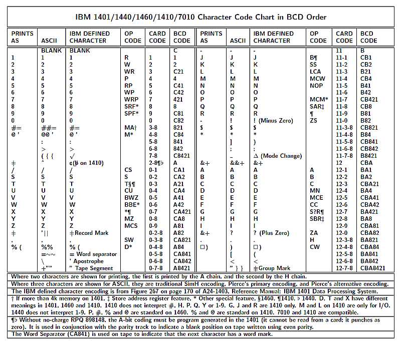
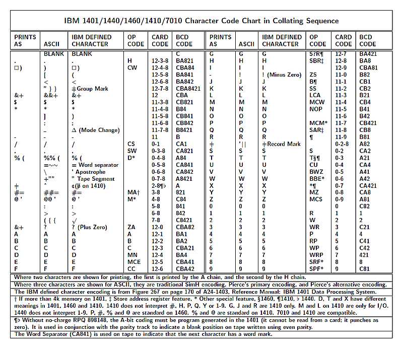
- Character Code Charts first in BCD order, then in collating sequence order.
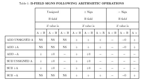
- B-field signs after arithmetic operations There's a shorter version of it on page 28 of the "Brownie Book," A24-1403. Dick Weaver gave me this version.
- 5 digit to 3 digit : 3 digit to 5 digit address conversions
Memory organizationThe basic unit of information is a six-bit character, consisting of a four-bit digit part (8-4-2-1) and a two-bit zone part (B-A). The addressable unit of memory consists of a character, a word mark (W), and a parity ("check") bit (C). These are written in manuals, and appear on the computer console, as CBA8421W. The memory cycle time is 11.5 microseconds. Models were manufactured with 1400, 4000, 8000 and 16000 characters of memory. Data representationFields of data are usually referenced by the character at the highest address. The character at the lowest address is indicated to be the end of the data field by having its word mark bit set.Character fields are stored with the first character at the lowest address and the last character at the highest address of the field. Numeric fields are stored with the high-order digit at the lowest address and the low-order digit at the highest address. The sign of the field is represented by zone bits in the low-order character: B-zone means negative, and any other combination, including no zone, is positive. Overflows are encoded by zone bits in the high-order character, in the order A, B, BA. During arithmetic operations the zone bits in other characters of the fields are ignored in operands, and cleared in results. AddressingAddresses are represented by three characters.Addresses less than 1000 consist of three digits. Addresses less than 4000 consist of three digits, plus overflows in the high-order character. Addresses above 3999 have zone bits in the low-order character. Writing the zone bits in the low-order and then high-order character in the order BABA gives the thousands part of the address in binary. Low zones High zones Thousands B A B A 0 0 0 0 0 0 0 0 1 1 0 0 1 0 2 0 0 1 1 3 0 1 0 0 4 0 1 0 1 5 0 1 1 0 6 0 1 1 1 7 1 0 0 0 8 1 0 0 1 9 1 0 1 0 10 1 0 1 1 11 1 1 0 0 12 1 1 0 1 13 1 1 1 0 14 1 1 1 1 15 IndexingA special feature called "advanced progamming" provides three index registers. These are actually stored in memory, at locations 87-89, 92-94, and 97-99.An address indicates indexing with zone bits in the middle character. If indexing is selected, the address used during execution of an instruction consists of the address specified in the instruction plus the contents of the specified index register. Indexing adds three cycles, and sometimes four, per address, to the instruction execution. B A Index register 0 0 None 0 1 X1 1 0 X2 1 1 X3 Address arithmeticAddress arithmetic is modular, or "wraps around," at 16000. Therefore to subtract a number X from an address, add 16000-X to it. |
IBM 1401 peripheralsDozens of peripheral devices could be attached to an IBM 1401.A basic system included a model 1402 card reader-punch and a 1403 printer. Bigger systems included model 729 or 7330 tape drives or model 1301, 1311 or 1405 disk drives. Peripherals for data communication, optical character recognition, check sorting, paper tape, ... were available. 1402 card reader-punchThe 1402 card reader-punch can read up to 800 cards per minute and punch up to 250 cards per minute.Cards can have rectangular holes punched in 80 columns and twelve rows. The top two rows are called 12 and 11, or Y and X. The bottom ten rows are called 0-9. Rows 12 and 11 are called zone rows and rows 0-9 are called numeric rows. Data are always read into positions 1-80 of memory, and always punched from positions 101-180 of memory. Relationship between card punches and character representations
1403 printerThe 1403 printer consists of a printing mechanism and a paper-advance mechanism.The printing mechanism consists of a bank of 132 hammers, a ribbon, and a chain of characters. Horizontal spacing of characters is ten per inch. The chain is contained within a removable cartridge. The chain is spun in front of the paper at high speed. When a character on the chain is at a print position at which that character is to be printed, the hammer strikes the paper from the back. The ribbon is positioned between the paper and the chain, resulting in an ink impression of the character when the hammer strikes. Three standard chains were available. The A chain is for business applications, and the H chain is for scientific applications. These chains had six copies of a 48-character set. With these chains, the printer could print up to 600 lines per minute. A numeric chain, having eighteen copies of only the digits plus six special characters allowed printing at up to 1200 lines per minute. Characters having 5-8, 6-8 or 7-8 representations (with or without zones) cannot be printed without special chains. The representations of the A and H chains, in Paul Pierce's ASCII encoding of BCD tapes, are
                8421 in hex, A chain               8421 in hex, H chain
Zone  BA | 0 1 2 3 4 5 6 7 8 9 A B C D E F  |  0 1 2 3 4 5 6 7 8 9 A B C D E F
none  00 |   1 2 3 4 5 6 7 8 9 0 # @ : > {  |    1 2 3 4 5 6 7 8 9 0 = ' : > {
zero  01 | ^ / S T U V W X Y Z | , % ~ \ "  |  ^ / S T U V W X Y Z | , ( ~ \ "
 11   10 | - J K L M N O P Q R ! $ * ] ; _  |  - J K L M N O P Q R ! $ * ] ; _
 12   11 | & A B C D E F G H I ? . ) [ < }  |  + A B C D E F G H I ? . ) [ < }
The only differences here are B-A (12) [&,+], 3-8 [#,=], 4-8 [@,'] and
A-4-8 (0-4-8) [%,(]. On a real A chain, B-A-4-8 (12-4-8) printed as a
character named "lozenge," a little box with pointed corners.
Data are always printed from memory positions 201-332. The paper advance mechanism can be set to advance paper at six or eight lines per inch. It can also skip to a position indicated by a punch on a paper control tape at 75 inches per second. Other peripheralsNone of the other peripherals transfer data to or from dedicated positions in memory. |
IBM 1401 registersAddress registersThe IBM 1401 processor has three address registers that the program can affect, and one optional address register the program cannot affect or examine. All address registers can be examined from the console.Index registers are actually memory fields, not proper registers. I-address registerThe I-address register contains the instruction address. It is incremented by the normal sequence of instruction execution, or changed by a branching instruction.A-address registerThe A-address register contains the address of the first operand of an operation. It is initially set from the A field of an instruction, and may be changed during execution of the instruction.B-address registerThe B-address register contains the address of the second operand and/or destination result of an operation. It is initially set from the B field of an instruction, and may be changed during execution of the instruction. If the advanced programming feature is installed, after an instruction that branches is executed, it contains the address following the branch instruction. This is useful for subroutine linkage.O-address registerIf the process overlap special feature is installed, the 1401 processor includes the O-address register, which is used during overlapped input/output operations. It is not affected by and cannot be examined by the program.Data registersThe 1401 processor includes three one-character data registers. They are used during instruction execution but cannot be otherwise affected or examined by the program.B registerThe B register is the register through which all data pass between the processor and memory.A registerThe A register contains a character from the first operand of an operation. During instruction fetching the B register is copied to the A register.OP registerThe OP register contains the instruction OP code.Instruction length registerThe instruction length register contains the instruction length. |
IBM 1401 instructionsInstruction representationInstructions are represented by consecutive characters in memory.The first character has a word mark. With three exceptions, the representation continues through characters at increasing addresses, up to but not including the next character that has a word mark. Instructions can have lengths of one, two, four, five, seven, or more than seven characters. Instruction lengths of three or six result in address decoding errors, which cause the processor to stop with the "check stop" lamp illuminated. The three instructions that do not need to be followed by a character with a word mark are five-character branch with blank D modifier, seven-character set word mark, and seven-character clear storage and branch. Instructions and their formats are summarized below. Instruction fieldsInstructions have from one to four fields.OP code fieldThe first character of every instruction is the operation code, or the OP code. It specifies the operation to be performed.A address fieldIf the instruction length is four or more, the second, third and fourth characters of the instruction are the A address field. If the first character is % or @ this is a device address. Otherwise, this is the memory address of a branch target in a branching instruction or an operand of an operation.B address fieldIf the instruction length is seven or more, the fifth, sixth and seventh characters are the B address field. This is the address of an operand of an instruction.D modifier fieldIf the instruction length is two, five, or more than seven, the final character is the D modifier field. It further specifies or modifies the operation. The D modifier of an instruction is taken from the A register. Therefore, if an instruction expects to use a D modifier character, but it doesn't have enough characters, the last one fetched is used as the D modifier. Instructions with operation codes of B or V use a D modifier if the instruction is one character or more than six characters. Instructions with operation codes of L or M use a D modifier if the A address field of the instruction begins with % or @ and the instruction is longer than six characters.Instruction summaryThe Dataflow manual provides detailed information about the instruction fetch phase, and about the method of operation of most instructions. It was not updated when the overall logic scheme was changed at serial number 25,000, and it does not include input/output.The Principles of Operation manual provides detailed information about each instruction.
D-modifier indicators for five-character branch
D Char  Autocoder  Unit Meaning
blank   BIN        1401 Unconditional -- no word mark needed in next char
1       BIN        1009 in run condition A24-3071-2 I-66
                   1011 punch in backspace operation
                   1011 reader parity indicator on
                   1231 auto select
                   1285 error
                   1412 control-check indicator on
                   1418 late read
                   1419 document to be read
                   1428 late read or late reading mode change
                   1445 printer error
                   7340 hypertape unusual end
                   7740 transmission complete with abnormal status
                   DDC  transmission error A24-3071-2 I-14
2       BIN        1009 buffer available A24-3071-2 I-66
                   1011 punch ready
                   1011 reader ready
                   1231 full buffer
                   1285 end of line
                   1412 reader-not-ready signal on
                   1418 ready to engage
                   1419 document under read head (PDS 4)
                   1428 ready to engage
                   7340 hypertape normal end
                   7740 transmission complete successfully
                   DDC  transmission ended by GMWM A24-3071-2 I-14
3       BIN        1009 good transmission occurred A24-3071-2 I-66
                   1011 punch not ready to receive data
                   1231 ready to read
                   1285 reader transporting
                   1412 read-check indicator on
                   1418 document under selected read station
                   1419 valid amount field
                   1428 document under selected read station
                   7340 hypertape control unit 7641 busy
                   7740 receive request
                   DDC  read request A24-3071-2 I-14
4       BIN        1009 reply-bad indicator on A24-3071-2 I-66
                   1011 punch not ready to read
                   1231 empty hopper
                   1285 marked line
                   1412 amount-field indicator on
                   1419 valid process-control field
                   7340 hypertape attention
                   7740 7740 attention
                   DDC  write request A24-3071-2 I-14
5       BIN        1009 error reply acknowledgement A24-3071-2 I-66
                   1011 punch overextended
                   1231 read error or overrun
                   1285 header information
                   1412 process-control indicator on
                   1418 document end
                   1419 valid account-number field
                   1428 document end
                   1445 printer busy
6       BIN        1009 program attention required A24-3071-2 I-66
                   1011 punch supply reel low or chad box full
                   1231 timing mark check
                   1285 ready to read a line
                   1412 account-number indicator on
                   1418 character on line
                   1419 valid transit-number field
                   1428 character on line
                   1445 carriage busy
                   DDC  write in progress A24-3071-2 I-14
7       BIN        1009 end of message A24-3071-2 I-66
                   1285 reader ready
                   1412 transit-number indicator on
                   1418 empty hopper and transport (end of file)
                   1419 valid serial-number field
                   1428 empty hopper and transport (end of file)
                   1445 carriage channel 9
                   DDC  read in progress A24-3071-2 I-14
8       BIN        1009 end of file A24-3071-2 I-66
                   1285 end of file
                   1412 document-spacing-check indicator on
                   1418 ready to read
                   1419 auto-select
                   1428 ready to read
                   1448 carriage channel 12
                   DDC  system A stopped A24-3071-2 I-14
9       BIN        1403 carriage tape channel 9
0       BIN        1404 validity error
#/=
@/'     BCV        1403 carriage tape channel 12
:
>       BIN        1448 end of block
{
^
/       BU         1401 unequal compare
S       BE         1401 equal compare
T       BL         1401 low compare
U       BH         1401 high compare
V       BIN        1301 disk error
                   1311 disk error
                   1405 read or write parity check or read back check error
W       BIN        1301 wrong-length record
                   1311 wrong-length record
                   1405 wrong-length record
X       BIN        1301 uniqual-address compare
                   1311 uniqual-address compare
                   1405 unequal-address compare
Y       BIN        1301 any disk-unit error condition
                   1311 any disk-unit error condition
                   1405 any disk-unit error condition
Z       BAV        1401 arithmetic overflow
|       BIN        1403 printer error (record mark)
,
%/(     BIN        1401 process check with process check switch off (%)
                   1440 I/O check stop switch off (maybe 1440 only)
~
\       BIN        1301 access busy
                   1311 access busy
"
-
J       BIN        1419 I/O channel-busy indicator
                   TAU  tape busy
                   SIO  serial input-output busy
K       BEF        TAU  end of reel (writing) or tape mark (reading)
L       BER        TAU  tape error
M
N       BIN        1301 access inoperable
                   1311 access inoperable
                   1405 access inoperable
O
P       BIN        1403 printer busy
Q       BIN        1407 inquiry request
R       BIN        1403 carriage busy
!                  1402 punch error
$
*       BIN        1407 inquiry clear
]
;
_
&/+     BIN        1442 last card (Reader unit 2)
A       BLC        1402 last card if SS A is on
B       BSS        1401 SS B
        BIN        7340 hypertape attention response
C       BSS        1401 SS C
D       BSS        1401 SS D
E       BSS        1401 SS E
        BIN        7340 hypertape end response
F       BSS        1401 SS F
G       BSS        1401 SS G
H       BIN        1402 reader busy
I       BIN        1402 punch busy
?       BIN        1402 reader error
.
)
[
<       BIN        1448 early warning
}
|
IBM 1401 address chainingAn important feature of the IBM 1401 that is useful for reducing the size of programs is address chaining.As an insruction of length greater than one is fetched, the second character is put into the first character of the A-address register. If there are third and fourth characters, they are put into the second and third characters of the A-address register. If the instruction length is one, the A-address register is not changed. If the instruction OP code is not L, M, Q or H, the second through fourth characters of the instruction are also put into the B-address register as they are fetched. Otherwise, the B-address register is not changed at this point. As an instruction of length greater than four is fetched, the fifth character is put into the first character of the B-address register. If there are sixth and seventh characters, they are put into the second and third characters of the B-address register. The Dataflow manual provides detailed information about the instruction fetch phase. Because of this method of changing the contents of address registers, if the contents of an address register after executing the previous instruction are the contents desired at the beginning of the next instruction, the address field need not be present. It is not possible to provide the B-address field and omit the A-address field. Chaining is frequently used to move or add adjacent fields, but it has many other uses. One that is not obvious is to chain BCE or BWZ instructions. The Principles of Operation manual provides detailed information about the contents of address registers after each instruction is executed. |
Loading programs in IBM 1401Programs can be loaded into IBM 1401 from cards, tape or the serial I/O adapter.Loading programs from cardsTo load a program from cards, put the cards in the card reader. Press check reset and start reset on the 1401 console, then press check reset and load on the 1402.The effect of pressing the load key on the 1402 is to set a word mark in location 1, clear all word marks in locations 2-80, read a card, and branch to location 1. Since every instruction has to begin with a word mark, the first card loaded has to start setting word marks for the rest of the program on that card. Fortunately, a seven-character set word mark instruction is one of three instructions that do not need to be terminated by a word mark in the next character. Very simple loaderA very simple loader, used for the diagnostic decks, loads one instruction or data field from each card. Bootstrapping the loader requires a very simple program on the first card:001 sw 8,12 008 r 1Which on the first card reads ,0080121001Each of the next cards loads one instruction or data field: 001 lca abc,xyz 008 r 1 012 * first character to load ... abc * last character to load at xyzwhich on the card reads LABCXYZ1001...The last card clears the read area and branches to the program using a seven-character clear storage and branch instruction: 001 cs xyz,80which on the card reads /xyz080 Autocoder loader formatThe Autocoder assembler produces cards in which data to be loaded are in columns 1-39, and instructions to load those data, and set word marks, are in 40-71. Usually, the instruction in 40-46 is a load instruction. Usually, the instructions in 47-67 are set word mark instructions, although sometimes the first one is a clear word mark instruction. Usually the instruction in 68-71 is read a card and branch to 40.To bootstrap this loader, Autocoder produces the following card: ....5...10...15...20...25...30...35...40...45...50...55...60...65...70. ,008015,022029,036040,047054,061068,072/061039 ,0010011040 1 1 1 1 1 1 1 1 1 1 1 1A simpler one is ....5...10...15...20...25...30...35...40...45...50...55...60...65...70. ,008047/047046 ,054061,068072,0010401040 1 1 1 1 1 1 1If a program has overlays, it's useful not to clear the word marks in the read area, so as to be able to continue loading. To enter a portion of a program without clearing the read area, columns 68-71 contain a branch instruction. The last card has a clear storage and branch instruction in columns 40-47. This is described in detail on page 51 in the Autocoder assembler reference manual. Loading programs from tapeTo load a program from tape, mount the tape on unit 1 and make it ready, press check reset and start reset on the 1401 console, and then press tape load on the 1401 console.When the tape load key is pressed, the 1401 reads one record from tape unit 1, with word marks, into location 1, and branches to location 1. It's not necessary to bootstrap this process in the same way as for loading from cards because records can be read from tape with word marks. It may be necessary, however, to provide that one record of the program reads the next one. Autocoder provides a loader that runs entirely in locations 1-80. The first record clears core: ....5...10...15...20...25...30...35...40...45...50...55...60...65...70. ,200/000H008V0052001L051115L/100099L%U1001R/007199 CLEAR STORAGE 1 1 1 1 1 11 1 1 The second record contains the loader for the remaining records: ....5...10...15...20...25...30...35...40...45...50...55...60...65...70. U%U1B.L%U1020RB001L.020 1 11 1 1 1 which is executed beginning in location 7. Subsequent records load data into core, and then load the next record by branching to location 7. This is described in detail in on page 51 the Autocoder assembler reference manual. Other formats for loading from cardsThe number of ways to load programs from cards is limited only by your imagination. The 1401 Fortran IV compiler uses a format in which word marks are represented on cards by the same character as is used on tape. There is no "read a card with word marks" instruction, so a loader program has to be provided. Here's one:
               job  Alternative boot loader -- uses SBR
               ctl  6611
     *
     * Boot loader.  On each program card
     * CC 1-3 give first address to load.
     * CC 4-5 give number of non-word-separator characters to process.
     * CC 7-70 are characters to be loaded, or word separator
     *         characters 0-5-8 preceding characters to get word marks.
     * Load CS xxx,080 atop read - read&6 to enter program, thus
     *  09907~/xxx080
     * or change the A-address at done&1 - done&3 to enter the program
     * without clearing the read area, thus
     *  13103xxx
     *
     * This runs in 96-199.  The start-up code from 200-218 is cleared.
     *
               sfx  1
               org  96
     k001      dc   001
     read      r
               sbr  move&3,007         Starting from address & 1
     loop      mcw  3,cwsw&3           Move ,,to,, address to cw or sw
               mcw  cw                 Move CW op code to cworsw
               mcw  3                  Move ,,to,, address to move
               s    read,5             Decr count of chars to process
               ma       read-1,003     Bump ,,to,, address
     done      bm   read,5             Read another card if all moved
     move      mcw  0-0,save           Pick up two characters
               mcw  save-1,0-0         Store character, B gets cc 1-3
     cwsw      cw   0-0                Either SW or CW, A gets cc 1-3
     addrs     ma   k001,move&3        Bump from address
               bce  *&5,save-1,~       word separator, 0-5-8
               b    loop               Process next character
               s    save-1             Clobber word separator
               bce  addrs,save,~       word separator, 0-5-8
               mcw  sw,cwsw            Prepare to set WM
               b    move
     cw        cw
     sw        sw
     save      equ  80                 Use cc 79-80 for work
     first     sw   79
               cs
               sw   1,4
               cs   read,*
               xfr  first
|
Switched BranchesThere are several ways for programs to change their paths of execution, what would now be done by setting and testing boolean or logical variables.Word marks as flagsWord marks can be set or cleared with four-character instructions, and tested with an eight-character instruction.
       sw   flag       turn on the branch
       cw   flag       turn off the branch
       bw   xyz,flag   branch to xyz if flag has a word mark
flag   dcw  #1
Characters as flagsCharacters can be used as flags, but this is somewhat less efficient than using word marks, since seven-character instructions are needed to change them, and a value to put into them has to be stored somewhere. An advantage is that they can have more than two values.
       mcw  @x@,flag     turn on the branch
       mcw  @y@,flag     turn off the branch, maybe turn a different one on
       mcw  @z@,flag     turn off the branch, maybe turn a different one on
       bce  xyz,flag,x   branch to xyz if flag is x
flag   dcw  #1
Modify the OP codeThe op code can be changed between branch and NOP
       mcw  branch,switch  turn on the branch
       mcw  nop,switch     turn off the branch
switch b    xyz            branch if the OP code is not NOP
The values to set into the OP code can be ordinary literal values, or OP
codes of instructions that don't change. A program always has branches
for other purposes. NOP is less commonly needed.
Switch branch with word marksThis is the most efficient method. Branches can be switched by setting and clearing word marks, either at the OP code of the D-modifier.Initially on branchAn initially on branch is implemented by a NOP followed by a branch. The branch is switched by setting or clearing the word mark under its OP code.
       nop
switch b    xyz     branch if switch has a word mark, else part of NOP
       cw   switch  turn off the branch
       sw   switch  turn it back on
Initially off branchAn initially off branch is implemented as a branch-on-indicator using an indicator that is never set by the processor, such as a group mark. The branch is switched by setting or clearing the word mark under the D-modifier.
switch  bin  xyz,}     branch if D-modifier has a word mark
        cw   switch&4  turn off the branch
        sw   switch&4  turn on the branch
|
Determining actual IBM 1401 core sizeWhen a one- or four-character clear storage instruction (/) is executed, if the value of the B-address register before execution is greater than 99 its value after execution is x99, where x is one less than the hundreds-thousands part of the value of the B-address register when the instruction began execution. For example, afterIf the value of the B-address register when execution of the instruction begins is less than 100, its value after execution is the address of the last installed character. This value will be 1399, 3999, 7999, 11999 or 15999, depending on the amount of core installed. If the indexing and store address feature is installed, the B-address register can be stored after a clear storage instruction. If it is stored after one clears starting from any address in the range 0-99, it contains the address of the highest-addressed character. |
Clearing core in IBM 1401Clearing fewer than 101 characters, down to x00To clear fewer than 101 characters, down to x00, useClearing a few hundreds of characters, down to x00To clear a few hundred characters, down to x00, use
       cs   332
       cs
Clearing many, or an indeterminate number, of hundreds of characters, down to x00There are three ways to clear core down to x00 using loops.Using compareAssume an address constant contains w99, where w is x-1.
loop   cs   top
       sbr  loop&3
       c    loop&3,adcon
       bu   loop
       ...
adcon  dsa  w99
This requires 23 characters.
If the code needs to be reused, put the top address to be cleared into
mcw &top,loop&3
or
sbr loop&3,top
This increases the requirement to 33 or 30 characters, respectively.
Using BCEIf the prior contents of a character in the bottom century to clear are known, and known not to be blank, it can be tested to determine whether that century has been cleared:
       mcw  *-6,xyz
loop   cs   top
       sbr  top&3
       bce  loop,xyz,M
This requires 23 characters.
If the value of xyz is known, that value can be tested at the bottom of the loop, and the MCW is not needed. This brings the requirement down to 16 characters. Using BWIf it is known that a character in the bottom century to be cleared contains a word mark, it can be tested to determine whether that century has been cleared:
       sw   xyz
loop   cs   top
       sbr  top&3
       bw   loop,xyz
This requires 20 characters.
If it is known that xyz has a word mark, the first instruction is not needed. This brings the requirement down to 16 characters. Using an index registerSo as not to require to change the A-address field at
loop   cs   0&x3
       sbr  x3
       ...
This requires putting the top address to clear into X3 instead of
Clearing down to xyzTo clear down to xyz, where xyz is not x00, the easiest way is to use an index register. Assume clearing is to start at xtu, where tu is greater than yz.
       sbr  x3,xtu
       sw   xyz
loop   mcw  @ @,0&x3
       sbr  x3
       cw   1&x3
       bw   loop,xyz
If X3 already contains an appropriate address, perhaps as a result of
using X3 to clear down to y00 where y equals x+1, the first instruction
can be deleted.
|
List of d-modifiers for BIN (5-character branch) instructions
BIN D modifiers

D cha r Punch Bits    Unit Meaning
blank   none  C------ 1401 Unconditional -- no word mark needed in the next char
1       1     ------1 1009 in run condition A24-3071-2 I-66
                      1011 punch in backspace operation
                      1011 reader parity indicator on
                      1231 auto select
                      1285 error
                      1412 control-check indicator on
                      1418 late read
                      1419 document to be read
                      1428 late read or late reading mode change
                      1445 printer error
                      7340 hypertape unusual end
                      7740 transmission complete with abnormal status
                      DDC  transmission error A24-3071-2 I-14
2       2     -----2- 1009 buffer available A24-3071-2 I-66
                      1011 punch ready
                      1011 reader ready
                      1231 full buffer
                      1285 end of line
                      1412 reader-not-ready signal on
                      1418 ready to engage
                      1419 document under read head (PDS 4)
                      1428 ready to engage
                      7340 hypertape normal end
                      7740 transmission complete successfully
                      DDC  transmission ended by GMWM A24-3071-2 I-14
3       3     C----21 1009 good transmission occurred A24-3071-2 I-66
                      1011 punch not ready to receive data
                      1231 ready to read
                      1285 reader transporting
                      1412 read-check indicator on
                      1418 document under selected read station
                      1419 valid amount field
                      1428 document under selected read station
                      7340 hypertape control unit 7641 busy
                      7740 receive request
                      DDC  read request A24-3071-2 I-14
4       4     ----4-- 1009 reply-bad indicator on A24-3071-2 I-66
                      1011 punch not ready to read
                      1231 empty hopper
                      1285 marked line
                      1412 amount-field indicator on
                      1419 valid process-control field
                      7340 hypertape attention
                      7740 7740 attention
                      DDC  write request A24-3071-2 I-14
5       5     C---4-1 1009 error reply acknowledgement A24-3071-2 I-66
                      1011 punch overextended
                      1231 read error or overrun
                      1285 header information
                      1412 process-control indicator on
                      1418 document end
                      1419 valid account-number field
                      1428 document end
                      1445 printer busy
6       6     C---42- 1009 program attention required A24-3071-2 I-66
                      1011 punch supply reel low or chad box full
                      1231 timing mark check
                      1285 ready to read a line
                      1412 account-number indicator on
                      1418 character on line
                      1419 valid transit-number field
                      1428 character on line
                      1445 carriage busy
                      DDC  write in progress A24-3071-2 I-14
7       7     ----421 1009 end of message A24-3071-2 I-66
                      1285 reader ready
                      1412 transit-number indicator on
                      1418 empty hopper and transport (end of file)
                      1419 valid serial-number field
                      1428 empty hopper and transport (end of file)
                      1445 carriage channel 9
                      DDC  read in progress A24-3071-2 I-14
8       8     ---8--- 1009 end of file A24-3071-2 I-66
                      1285 end of file
                      1412 document-spacing-check indicator on
                      1418 ready to read
                      1419 auto-select
                      1428 ready to read
                      1448 carriage channel 12
                      DDC  system A stopped A24-3071-2 I-14
9 BC9   9     C--8--1 1403 carriage tape channel 9
0       0     C--8-2- 1404 validity error
=       3-8   ---8-21
' BCV   4-8   C--84-- 1403 carriage tape channel 12
:       5-8   ---84-1
>       6-8   ---842- 1448 end of block
{       7-8   C--8421
^       none  --A----
/ BU    0-1   C-A---1 1401 unequal compare
S BE    0-2   C-A--2- 1401 equal compare
T BL    0-3   --A--21 1401 low compare
U BH    0-4   C-A-4-- 1401 high compare
V       0-5   --A-4-1 1301 disk error
                      1311 disk error
                      1405 read or write parity check or read back check error
W       0-6   --A-42- 1301 wrong-length record
                      1311 wrong-length record
                      1405 wrong-length record
X       0-7   C-A-421 1301 uniqual-address compare
                      1311 uniqual-address compare
                      1405 unequal-address compare
Y       0-8   C-A8--- 1301 any disk-unit error condition
                      1311 any disk-unit error condition
                      1405 any disk-unit error condition
Z BAV   0-9   --A8--1 1401 arithmetic overflow
|       0-2-8 --A8-2- 1403 printer error (record mark)
,       0-3-8 C-A8-21
(       0-4-8 --A84-- 1401 process check with process check switch off (%)
                      1440 I/O check stop switch off (maybe 1440 only)
~       0-5-8 C-A84-1
\       0-6-8 C-A842- 1301 access busy
                      1311 access busy
"       0-7-8 --A8421
-      11     -B-----
J      11-1   CB----1 1419 I/O channel-busy indicator
                      TAU  tape busy
                      SIO  serial input-output busy
K BEF  11-2   CB---2- TAU  end of reel (writing) or tape mark (reading)
L BER  11-3   -B---21 TAU  tape error
M      11-4   CB--4--
N      11-5   -B--4-1 1301 access inoperable
                      1311 access inoperable
                      1405 access inoperable
O      11-6   -B--42-
P      11-7   CB--421 1403 printer busy
Q      11-8   CB-8--- 1407 inquiry request
R BPCB 11-9   -B-8--1 1403 carriage busy
!      11-0   -B-8-2- 1402 punch error
$      11-3-8 CB-8-21
*      11-4-8 -B-84-- 1407 inquiry clear
]      11-5-8 CB-84-1
;      11-6-8 CB-842-
_      11-7-8 -B-8421
+      12     CBA---- 1442 last card (Reader unit 2)
A BLC  12-1   -BA---1 1402 last card if SS A is on
B BSS  12-2   -BA---2 1401 SS B
                      7340 hypertape attention response
C BSS  12-3   CBA--21 1401 SS C
D BSS  12-4   -BA-4-- 1401 SS D
E BSS  12-5   CBA-4-1 1401 SS E
                      7340 hypertape end response
F BSS  12-6   CBA-42- 1401 SS F
G BSS  12-7   -BA-421 1401 SS G
H      12-8   -BA8--- 1402 reader busy
I      12-9   CBA8--1 1402 punch busy
?      12-0   CBA8-2- 1402 reader error
.      12-3-8 -BA8-21
)      12-4-8 CBA84--
[      12-5-8 -BA84-1
<      12-6-8 -BA842- 1448 early warning
}      12-7-8 CBA8421

# Pierce's alternate BCD encoding:
#
# Numeric     b 1 2 3 4 5 6 7 8 9 0 3 4 5 6 7
# Rows        b                     8 8 8 8 8
# ===========================================
# No zone       1 2 3 4 5 6 7 8 9 0 = ' : > {  000-017 = 00-0F
# 0  zone A   ^ / S T U V W X Y Z | , ( ~ \ "  020-037 = 10-1F
# 11 zone B   - J K L M N O P Q R ! $ * ] ; _  040-057 = 20-2F
# 12 zone BA  + A B C D E F G H I ? . ) [ < }  060-077 = 30-3F
#
# | is 0-2-8, and ^ has no input punch (it may punch as zero
# on output).  On other systems it may be 2-8.
|
Character Code Charts first in BCD order, then in collating sequence order.
|
B-field signs after arithmetic operations
|
5 digit to 3 digit : 3 digit to 5 digit address conversions
On Tue, 2015-01-27 at 11:05 -0800, Ken Shirriff wrote:
> What's the easiest way to convert a 5-digit number to a 3-character
> address in a program?
>
> I understand how the zone bits encode the upper digits of the address.
> E.g. if I have the number 12345, the corresponding address is 34E (or
> something like that). But how can I do this in code? I can think of a
> couple ugly ways to do it:
>
>
> 1. Do various comparisons and set the appropriate zone bits. E.g. test
> if address >= 12000, 8000, 4000 and set zone bits. Then test if the
> remainder is >= 3000, 2000, 1000.
> 2. Use the MA (modify address) instruction in a loop, subtracting 1000
> from the number and adding 1000 to the base address each time.
>
>
> But is there an easy way to do this?
>
>
> Thanks,
> Ken

Van Snyder responded with the following

The attachments have my collection of routines to convert 3-to-5 and
5-to-3.

--------------------------------------------------------------
               job  Convert five-digit number to an address
               ctl  6611
     x1        equ  089
     five      equ  205
     three     equ  210
               org  336
     zones     dcw  @2skb@
     adr       dcw  #5
     number    dcw  #5
     start     sw   three-2
               lca  &15999,number
     outer     mcw  number,adr    Number to convert
               b    conv          Convert it to an address
               mcw  adr,three
               mcs  number,five
               w
               s    &1000,number  Subtract 1000
               bm   two,number    q. done
               b    outer         no
     two       lca  &15999,number
     outer2    mcw  number,adr    Number to convert
               b    conv2         Convert it to an address
               mcw  adr,three
               mcs  number,five
               w
               s    &1000,number  Subtract 1000
               bm   fast,number   q. done
               b    outer2        no
     fast      lca  &15999,number
     outer3    mcw  number,adr    Number to convert
               b    conv3         Convert it to an address
               mcw  adr,three
               mcs  number,five
               w
               s    &1000,number  Subtract 1000
               bm   done,number   q. done
               b    outer3        no
     done      h    done
               ltorg*
     *
     * Smallest routine to convert the five-digit number in adr to
     * a three character address, in place.  Needs the digit part
     * of the last character of the address of ZONES to be nine.
     *
     conv      sbr  convx&3
               bav  *&1           turn off overflow
     loop      a    @96@,adr-3
               bav  loop
               mz   adr-4,adr
               mn   adr-3,*&4
               mz   zones-0,adr-2
     convx     b    0-0
               ltorg*
     *
     * One that works similarly, but uses X1 and doesn't need ZONES
     * to be at a particular location.  Saving and restoring X1
     * would make it bigger and slower.
     *
     conv2     sbr  conv2x&3
               sbr  x1,0
               bav  *&1           turn off overflow
     loop2     a    @96@,adr-3
               bav  loop2
               mz   adr-4,adr
               mn   adr-3,x1
               mz   zones-9&x1,adr-2
     conv2x    b    0-0
               ltorg*
     *
     * Fastest routine to convert the five-digit number in adr to
     * a three character address, in place.  Uses X1.  Would be
     * slower and 14 characters longer if it saved and restored x1.
     *
     conv3     sbr  conv3x&3
               mcw  adr-3,x1
               mcw  @0@
               mz   hzone-15&x1,adr-2
               mz   lzone-15&x1,adr
     conv3x    b    0-0
     hzone     dcw  @9zri9zri9zri9zri@
     lzone     dcw  @9999zzzzrrrriiii@
               end  start

-----------------------------------------------------

and

------------------------------------------------------
               job  Convert three-character address to five digits
               ctl  6611
     from      equ  205
     start     lca  @999@,from         First address to convert
     outer     mcw  from,to
               b    c3to5              Convert it
               mcw  to,215
               mcw  from,to
               b    c3to5s             Convert it
               mcw  to,225
               mcw  from,to
               b    c3to5f             Convert it
               mcw  to,235
               mcw  from,to
               b    c3to5x             Convert it
               mcw  to,245
               w
               ma   a1k,from           Bump it by 1k
               c    from,@999@         Q. Wrapped around
               bu   outer              No
     done      h    done
     a1k       dsa  1000
               ltorg*
     *
     * Fast routine to convert the three-character address at
     * ,,to,, to a five-digit address, in place.
     *
     c3to5     sbr  exit&3
               s    to-3               Clear thousands digits
               mz   to,to-4            Low zone to accumulate
     loop1     bwz  loop1x,to-4,2      Q. low zone remaining
               a    @?4@,to-3          Yes, add 4k per low zone
               b    loop1
     loop1x    mz   to-2,to-4          High zone to accumulate
     loop2     bwz  loop2x,to-4,2      Q. high zone remaining
               a    @?1@,to-3          Yes, add 1k per high zone
               b    loop2
     loop2x    za   to&1               Clear zones
     exit      b    0-0
     to        dcw  #5
               dc   #1
               ltorg*
     *
     * Smallest routine to convert the three-character address at
     * ,,to,, to a five-digit address, in place.
     *
     c3to5s    sbr  exits&3
               mcw  k00,to-3           Zero high digits, leave no zone
     loop1s    za   to&1,test&1        Copy digits only
               c    to,test            Q. Address all digits
     exits     be   0-0                Yes, zones all gone
               ma   am1000,to          MA -1000 from address
               a    k1,to-3            Bump thousands
               b    loop1s
     test      dcw  #3
               dc   #1
     k00       dcw  00
     am1000    dsa  16000-1000         -1000
     k1        dcw  1
     *
     * Faster routine to covert the three-character address at
     * ,,to,, to a five-digit address, in place.
     *
     c3to5f    sbr  exitf&3
               mcw  k00,to-3
               bwz  lowf,to-2,2
               bwz  high2,to-2,k
               bwz  high1,to-2,s
               a    *-6,to-3
     high2     a    *-6,to-3
     high1     a    *-6,to-3
     lowf      bwz  donef,to,2
               bwz  low2,to,k
               bwz  low1,to,s
               a    &4,to-3
     low2      a    &4,to-3
     low1      a    &4,to-3
     donef     za   to&1             Clear zones
     exitf     b    0-0
               ltorg*
     *
     * Fastest routine to covert the three-character address at ,,to,,
     * to a five-digit address, in place, but it uses all three index
     * registers.
     *
     c3to5x    sbr  exitx&3
               lca  @0020000400006@,99
               mz   to-2,*&3         Set index register for thousands
               mcw  thou,to-3
               mz   to,*&3           Index register for 4-thousands
               a    thou4,to-3
               za   to&1             Clear zones
     exitx     b    0-0
     thou      dcw  00
               dcw  01
               dcw  02
               dcw  03
     thou4     dcw  00
               dcw  04
               dcw  08
               dcw  12
               end  start
|