Schedule October 2008

return to main 1401 Restoration Page
go to Team Bios

Contents:
Wed Oct 1 - General, Thurs Oct 2 - tape team
Wed Oct 8 - General, Thurs Oct 09 - tape team, Sat Oct 11 - 2nd Sat
Wed Oct 15 - General, Thurs Oct 16 - tape team
Wed Oct 22 - General, Thurs Oct 23 - tape team, Sat Oct 25 - 4th Sat
Wed Oct 29 - General, Thurs Oct 30 - tape team


Wed October 01 - general

E-mail from Grant Saviers - relative to pictures here.
The basic repairs are complete. I bought new bearings for both ends and will leave the gear removal and that end bearing replacement to Frank.

I machined the worn shaft and sleeved it with a 0.016 thick wall sleeve and locktite'd it on. The sleeve was made to be a snug fit to the new bearing but they should be attached with a small drop of light hold loctite to prevent them spinning and wearing the shaft again.

I made a new rubber tire. The old one measured about 1.1" diameter and was fairly soft so I picked a similar 0.375" stock I happened to have. Machining this rubber is about impossible so I punched the id undersize and stretched the tire onto the brass slider.

What I don't know is what the "new" od should be? Right now it is 1.27" To make it smaller I have to grind or sand off material. This is a very messy process so I want to do it only once.

After the final od is obtained, I will glue the new tire to the brass slider. The original tire was molded on and it appears from the design there was more concern about it being run off the brass sideways than rotary slipping.

Or I can drop it off tomorrow "as is" and Frank can do the rest. Let me know.

Grant

Reply to above by Frank King
Thanks Grant.

It sounds perfect.
I will take your advice about the Locktite.
As I was checking the plate the rubber runs on. I found that the spring that loads the plate against the rubber
has greater than 1/4 inch movement.
This would leave the diameter of the rubber wheel a tolerance of greater than that.

Thanks again for the fix.
Frank


Attendees: New: Jim Hartley, Ron Williams, Bob Erickson, Frank King, Allen Palmer, Judith Haemmerle, Glen Lea, Joe Preston, Robert Garner

* DE 1401

  • Having run without fault for 16 consecutive weeks now, the 729 and/or TAU started generating errors. The system otherwise runs BigPrint demo just fine.
  • Allen pulled out the defective power supply in the 2nd Model V 729. It's now on Dr. Ed's in-patient table. ;-)
  • Robert updated his write-up (incl pictures) of the set-by-step procedures for turning on the 1401 and running a demo program. (I'll post on web site when ready.)
  • This was perfect opportunity for a new volunteer(!), Jim Hartley, to see how to push buttons, be hopeful, align the 1403, get confused, get excited, etc.. ;-)
* CT 1401
  • Loading from the 1402 is still generating read check parity compare errors on the last, 12'th row holes.
  • Since the card data is being properly read into core, and Ron and Robert couldn't find any defective 1401 circuits when triggering with scope, we herby declare that it's a 1402 problem. We'll need to wait for Bill's fine hand at timing the reader, or otherwise exerting his influence.
  • This time card loading did not result in last week's frustrating destructive storage scans.
  • Joe and Frank decided that the Model II 729 switch contacts in the vacuum column bellows can be cleaned as they are.
  • During the week, Grant repaired Frank's 1403 paper roller shaft at his world-class machine shop.
  • Frank extracted the same shaft out of the spare CT 1403 and decided it would be easier to make the repair by merging pieces from each.
  • Robert & Frank met with Karen Kroslowitz, Registrar and Alex Bochannek, Curator, to discuss procedures for documenting the extraction or swapping of parts from the spare CT 1401 units, currently being stored in invisible storage (as we're out of room in the restoration room).
  • Bob Erickson and Judith did preventive maintenance on the 513 reproducing punch, which is working again. Amazing!
  • Jim started getting up to speed by learning how to toggle in a branch instructions on front panel.
  • (The 1401 instruction set and console are like nothing out there today or in the near past!)
  • 14 faulty SMS cards have been replaced in the CT 1401 to date.
  • (Given the DE 1401's SMS card annual failure rate of ~ 0.12%, the CT 1401 could have accumulated up to 45 defective cards during the 13 years since last running in 1995.)
  • Many instructions are operational in 1401 CPU, including multiply.


Thursday October 02 - Tape Team

Thursday, Oct. 2, 2008 - (Ron W., Jeff S., Sam S. and I)

There were reports of tape troubles with the German 1401, so we worked on it today.
  • Initially, we wrote records from the TAU CE panel to tape (a real 729).
  • We did not see any errors related to the B-bit, however, many other types of errors were being reported. It seemed like an error occurred about every 15 records and the type of error that was occurring changed every 2 minutes.
  • After the machine warmed up, the error indicator was on solid and would not reset. We traced this problem to a bad card in the error detection circuit. A transistor became leaky enough that it could no longer hold a logic '1' level. (about 2V instead of Gnd)
  • We now have several bad TAU cards waiting to be repaired. We are burning through the spares that came with the CT 1401. It would be nice if someone could take a shot at repairing them.
  • Even with the card replaced, the 1401 still could not  write and read back records to the 729 without very frequent errors.  (mostly tape runaway on Backspace operations and short records containing garbage being returned when written records were read back)
  • We moved the Tape Drive Emulator from the CT to the DE 1401. We needed to reset the +P interface reference voltage on the emulator. The two 1401s are different enough that their reference voltages are incompatible.
  • The 1401 was able to perform thousands of Write-Backspace-Read sequences to the Emulator without a single error.
  • Ron programmed the 1401 to alternate performing the Write-Backspace-Read sequence between the Emulator and the 729. All sequences to the Emulator ran correctly. Nearly every sequence to the 729 resulted in a short record containing garbage being read back. Typically the read back resulted in one to three A-8-2 characters, regardless of what was written.
  • We also tried the new T1-3/4 indicator lamps. They are about as bright as he weak lamps that we want to replace. I will search for some T2 lamps that are brighter. (One reason the T1-3/4 lamps are dim is that they are too small to be close to the front panel.)
We believe that there is something seriously broken in the 729. If Allen doesn't find the problem next Wednesday, we will start investigating inside the 729 next Thursday.

Regards,
Bob Feretich


Wednesday October 08 - General

  • Present were: Ron Williams, Bob Erickson, Frank King, Allen Palmer, Glen Lea, Joe Preston, Robert Garner, Ed Thelen - you know - the usual suspects - Judith called in ill -

  • Ed Thelen came in all hot to trot to fix that +12 volt 1.5 amp 729 mod 5 tape unit power supply. Glen et al had removed the 85 pound power supply box for easier access last week. A little sub-assembly in the top part is the sick +12 power supply with heat sink, 022 power transistor, component card and SMS regular card. I got out the big load resistor chassis lent to us by the PDP-1 group
    - hope they forgot who they lent it to -
    and verified that the power supply was still sick - bumber - it still was :-((

  • Well, it just gotta be that big pass transistor - it has like 13.4 volts on the collector, seemingly a 1.4 bias for conduction on the base, and the emitter is at ground - the thing just has to be open. I waved at the schematics - hoping to convince everyone of my position - Ron Williams said something rude like "Yeah - you just want to share the guilt" - he knows me too well !! Glenn and I removed screws and loosened the thing up as much as possible - short leads to the adjustment pot and pass transistor made access inconvenient. Frank King has good hands and recent experience and got volunteered to remove the just-gotta-be-sick transistor.

  • I noticed there was no heat transfer paste between the old type 022 transistor that Frank removed and the heat sink - found a Radio Shack that had some -
    By that time, Robert Garner was trying to test the old transistor with his transistor tester - he was saying something like "Maybe we will have to read the book." I left for Radio Shack in a hurry, not wanting to be involved with reading instructions !!
    Like How low can you go??

  • Got back from Radio Shack, and found the diagnosis was that the suspect transistor was "GOOD", and it was ready to re-install. OK - I did not read the book, and can't check the transistor. Frank resolders and reinstalls the re-assembled assembly - and there is no change - still about 3.4 volts under light load, 2.4 volts into a 20 ohm resistor, 1.2 into a 10 ohm resistor :-((

  • OK - you give it a think -
    The writing is Allen's measurements, the note about the voltage across C-3 with the connection to CB15(+12v) open. At least that is what I think he said - which it should be. Not sure about the 3.20v notation near by.
    Overview

    Detail

    Values
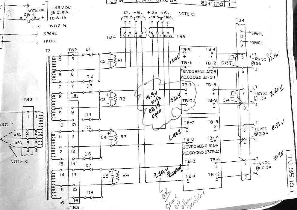
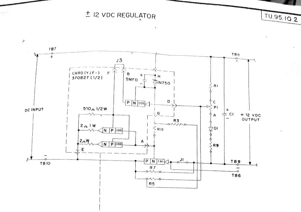
    After reading the above, Allen Palmer clearifies :
    The 3,2v going into the +12v power supply is the reading with the cb closed. what that means is that the problem is not .. good input voltage and bad output. what it does mean is that the voltage going into the +12v regulator is being pulled down to 3.2 volts. The output is the same as the input ... 3.2v This should help in the determination of the problem.
    allen
    Suggestions accepted - should I offer a reward?
    My plan for next session is to parallel that "good" transistor with a hopefully good spare :-||
    Unless you have a better idea?

  • And Allen Palmer - found that the potentiometer, wired as a variable resistor, in the DE 1401 Tape Adaptor Unit was VERY noisy, and maybe the cause of some trouble. So, back to Radio Shack, to get a pot. When we get back we find that the mounting screw part of the pot is shorter than required in the TAU because of the multiple layers of metal and the plastic faceplate with markings is too thick. The old pot had a much longer threaded section. Allen is looking in the various thick electronics catalogs for a pot with the correct form factor :-((

  • As we few remaining left Allen and his catalogs, we mentioned that the day was not very successful - maybe a total loss.

    Bob Erickson mentioned that Joe Preston ruined our today's record of non-accompishment. Apparently he got one of the CT tape units responding to the CT TAU (Tape Unit Adaptor) control panel.

  • Ron Williams pointed out that the CT 1401 has all memory working and responds correctly to many commands, including multiply but not divide, - but the 1402 card reader is really flakky - like it gets read checks on any punched card where there is an odd number of holes in a column - the card reads into memory correctly but the card read check circuity in the 1401 processor has a problem :-((

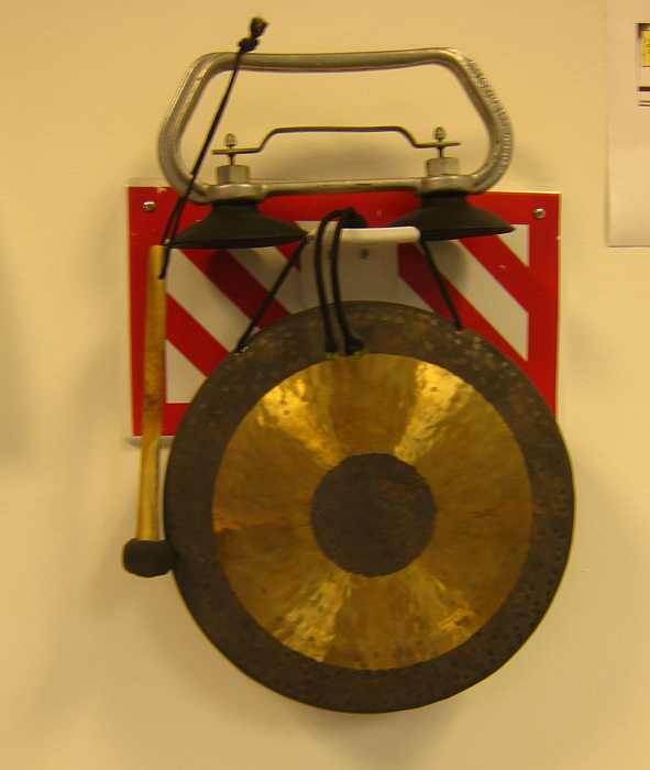
  • The new lunch time calling system - folks tend to get all wrapped up in their work - and/or get neckties and body parts caught in machinery. Therefore Robert Garner brought in this high tech solution. (Batteries were not included) The funny wire looking thing, with the two black suction cups is a "floor puller" used to lift sections of the already raised floor - like to look for wires or hidden goodies -
    Background - near the door - The FirstAid kit may have said something about "Grain Alcohol flavored with Juniper Berries". Sounds natural, must be good for you - Did Ron Williams supply this? - he is always ginning up something - 
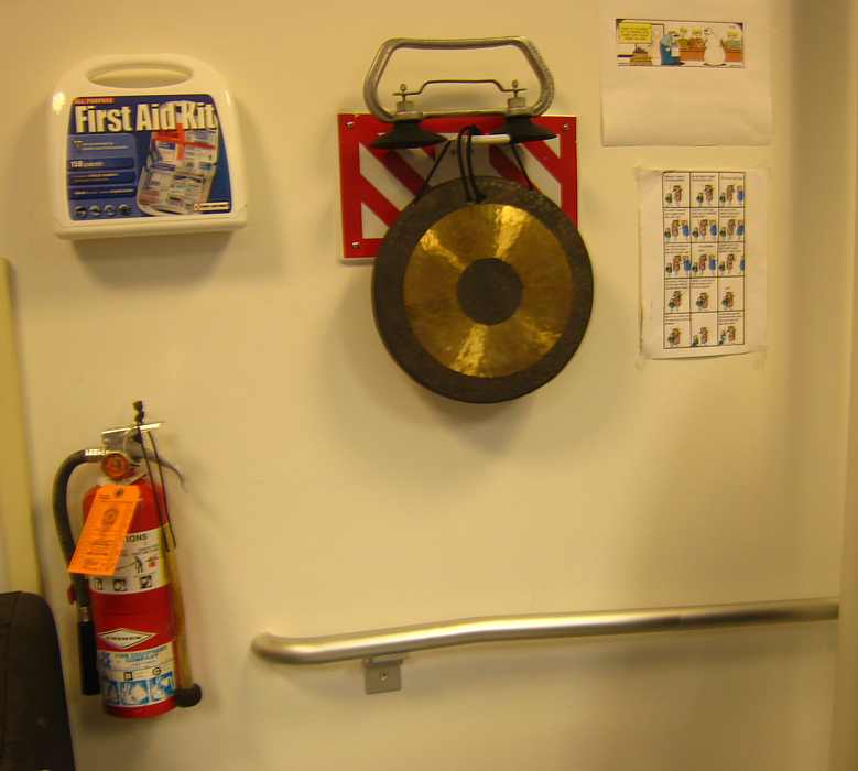
The red tank at the lower left can be used for emergency beer cooling or other emergency services -


Thursday October 09 - Tape Team

TAU debug status - Thursday, 10-9-08 (Jeff S., Sam S., and I)

Allen reported that the 729 on the German system was working, so we moved the Emulator back to the Connecticut system.
  • We successfully read records from the Emulator, one at a time, from the TAU control panel. However, "continuous read" would fail after a few records. We also noticed that Tape Mark records (a read beyond the end of the tape results in the Emulator creating a single character record containing a Tape Mark character) were being received as 8-4 rather than 8-4-2-1. We decided that these problems would be more easily troubleshot by running a program from 1401 memory rather than by working with the TAU CE Panel.
  • We tried to run a Tape Write instruction loop from memory. The loop ran, but the Emulator was never "Selected" on the tape channel.
  • The Selection logic is not inside the TAU. It is part of the 1401 OP Decode logic (gate 02A2). I had not investigated that logic before so it took quite while to determine what it was trying to do, but eventually we figured it out and found the bad card. A gate in an IO selection latch failed and the tape logic believed that the selection signal was intended for the serial IO port rather than the tape port.
  • After the card was replaced, we were able to write several hundred records from the 1401 memory to the PC.
  • Next week we will work on Tape Read instruction.
  • We also determined that the "Selected" indicator on the Virtual Tape Drive Console was not being turned on because its status bit was not being set by the Emulator firmware.
Regards,
Bob Feretich


Saturday October 11 - 2nd Saturday


Wednesday October 15 - General

After reading my sorry tale of trouble shooting above, John Van Gardner offered this unsympathetic cartoon. :-((
"While reading about your bout with the 729 power supply last Wednesday, I could not help but think about something I kept over my desk before I retired."

  • Present were: Ron Williams, Bob Erickson, Bill Flora, Allen Palmer, Glen Lea, Joe Preston, Stan Paddock, Robert Garner, Ed Thelen

  • Ron Williams, Bob Erickson, Bill Flora continued with the struggle to get the CT 1402 card reader working well -

  • Allen Palmer and Ed Thelen continued with the struggle to get the sick 729 tape drive +12 volt power supply working. It went sick about a month ago - we can report the cartoon above is likely "on-track".

  • The high point of the day is the continued success that Joe Preston has with one of the CT 729 Mod 2 tape drives. Today he reported that it appears to be writing tape, as controlled by the Tape Adapter Unit (TAU).
    Apparently the tape instruction decode to drive the TAU is not working. Ron Williams is full time on the 1402.

  • Ron Williams and Stan Paddock combined a hardware option (1403 print with out advancing the paper) with a BIG PRINT mod to provide overstrike printing (double hitting of the paper) to intensify the visitor's name on the printout. Apparently the 1401 was already wired for this - inserting two SMS cards into blank slots activated the change

  • Fun-n-games. A visitor had heard that an IBM card with all the punch positions punched out settled flatly while falling, in contrast to the side-to-side oscillations of an unpunched IBM card. Why not try it - be our own "Myth Busters" ;-)) So the guest punched almost all the 80 x 12 = 960 holes (It is hard to be purfekt.)
    The proof is in the pudding - and indeed, a laced card settles with very little side to side dynamics. Now, who would have asked? Who would have guessed? Somebody had too much time?


Thursday October 16 - Tape Team


Wednesday October 22 - General


Thursday October 23 - Tape Team

TAU Debug Status - Thursday, Oct 23rd (Jeff S., Sam S., Ron W., & me)
  • We determined that the Read Cond indicator lamp had burnt out and replaced it.
  • The TAU CE panel Start switch was intermittently failing so we replaced it.
  • A problem that disappeared last week was back today. We were able to make it a solid fail by:
    1. Reseting he TAU.
    2. Rewinding the virtual tape to the load point.
    3. Starting a Read Cont operation from the CE panel.
    4. Stopping the Read Cont by clicking Disc.
    5. Starting another Read Cont operation.
The failure would occur on he second record read by step 5 above. The TAU would begin to read the second record only .8 to 1.2 milliseconds after it dropped "GO" for the first record. The TAU must at least allow 2 milliseconds between operations for the tape to stop. The problem is sensitive to the setting of the "Go Down" pot position. The circuit for "Go Down" uses two single shots that tie into a rats nest of feedback logic. Replacing or retuning the single shots didn't help.

Hopefully the problem will be back again next week so we can shoot it.

Also:
  • Ron, turned on the German 1401 and the room filled with the smell of burning electronics. We think that the rewind motor in the 729 was the culprit.
  • We noticed that a heat sink on the output side, upper left corner, of the CT 1403 printer was very hot even though the printer was powered off. I don't know if this is normal or not.
Regards,
Bob Feretich


Saturday October 25 - 4th Saturday


Wednesday October 29 - General


Thursday October 30 - Tape Team

TAU Debug Status - Oct. 30, 2008 (Jeff S., Sam S., Grant S. and me)
We continued debug on the CE Panel Read Continuous problem that I reported last week. We are fairly certain that the problem is in the retriggerable "single shot" that is supposed pace continuous CE panel operations (NB@02A1D11 71.71.61 block 4A). We have replaced the card, trying the two spares and the card from the German 1401. The replacements do not fix the problem. Normally this would tell us that the card is good, and the problem is elsewhere in the circuit, but we cant see how any of the other logic in the area could be causing the symptoms we are seeing.

Logic analysis:
There are a lot of signals involved, but I believe the important sequence is...
  1. When a Read Continuous operation is stated, a "manual read op" is issued. This operation completes successfully. During this operation, the TAU activates its BUSY signal. The busy signal is deactivated when "GO" is dropped. This appears to be working correctly.
  2. The drop if the BUSY signal triggers the "single-shot", which is to create a 10 millisecond (minimum) to 100 millisecond (maximum) pulse. The pulse width is controlled by the "GO DOWN" potentiometer on the CE panel.
  3. The fall of this pulse triggers the next tape operation, which causes the TAU to activate BUSY until it completes the operation.
  4. Then, the drop of BUSY ... (Go to step two above.)
When we examine a stream of pulses created by the single-shot, pulses 3 through N are uniform and many milliseconds wide. Pulse 2 is about 90% of the width of pulse 3. Pulse 1 is very narrow (often less than one millisecond wide). By probing pin E of the single-shot, we see that the down level viewed on this pin starts at about -12V and rises to about -8V. It stabilizes at -8V during the second pulse. We believe that the shift in this "down level" is causing the variation in pulse widths.

We know that pulse widths less than about 1.5 milliseconds violate the tape "stop" timing. (The previous tape read or write operation is still in progress for about 1.5 milliseconds after the TAU drops busy. This is the overlappable period at the end of tape operations.) For the circuit to work properly the minimum pulse generated from the single-shot must be greater than 1.5 ms. The note at the bottom of the ALD page states that the single-shot should be adjusted so that the minimum pulse is 10 ms (with the GO DOWN pot set at its fastest position). We are unable to adjust the single-shot so that its minimum pulse width is >1.5ms.

We need somebody who knows more than us about circuits to look at this single-shot circuit and tell us why it can't be set to produce a consistent pulse width that is >1.5 ms.

Ron, can you examine it?

Regards,
Bob Feretich


Go to
November 2008
go to Team Bios