Schedule June 2008
return to main 1401 Restoration Page
go to Team Bios
Contents:
Wed June 4 - General
We also "confiscated" the TEK 535 that was stored under the desk in the 1401
room. We will use it as an illustrative "period" piece of test gear. Another
member of the Team volunteered to donate a "period" cart for the 535.
Thanks to Len for obtaining the TEK 2465 from SLAC and the 1401 Team for the TEK 535!!!
Cheers,
Wed June 11 - general
Wed June 18 - General
Wed June 25 - All hands meeting, general
Old Business - Yellow Wires in CT1401
All Hands Meeting
Reminder that our next 1401 restoration all-hands meeting is next Weds,
June 25th, 10 am - 1 pm, in the Boole conference room (upstairs).
Please RSVP to me so I can give Jim an estimate head count for lunch.
Current agenda:
Wed June 04 - general,
Wed June 11 - general,
Wed June 18 - general,
Wed June 25 - Yellow Wires, All hands meeting, general,
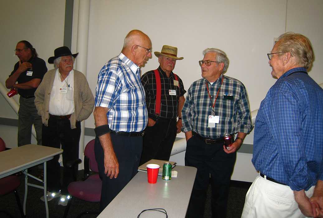
Present were Ron Williams, Bill Flora, Frank King, Joe Preston, Stan Paddock, ...
Bob Feretich reinstalled the -20 V supply
and removed the 3 volt marginal supply. (1402)

Frank continued work on the 1403.

(including Buzz, Scott, Arnold, Rolf, Van, Macklin, Fran, and Shel.)
Steve [Russell] and I checked out the scopes in the 1401 room(s) today. We did a cursory
checkout of the (4) channel TEK 2465 - and all the major functions we tested
worked O.K. We will use it for debugging the PDP-1. We moved it to the PDP-1
demo room.
Lyle
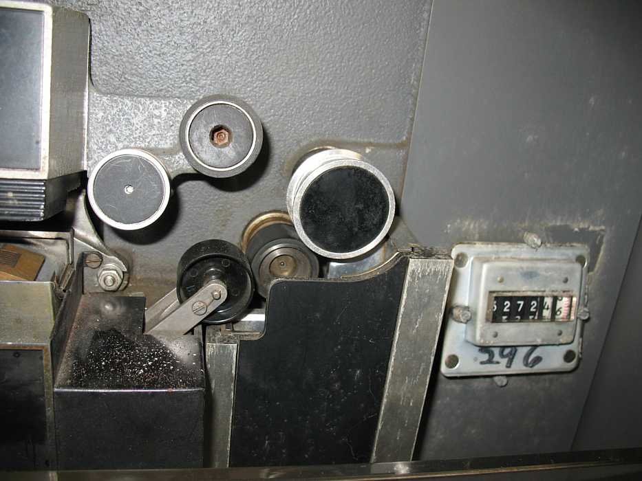
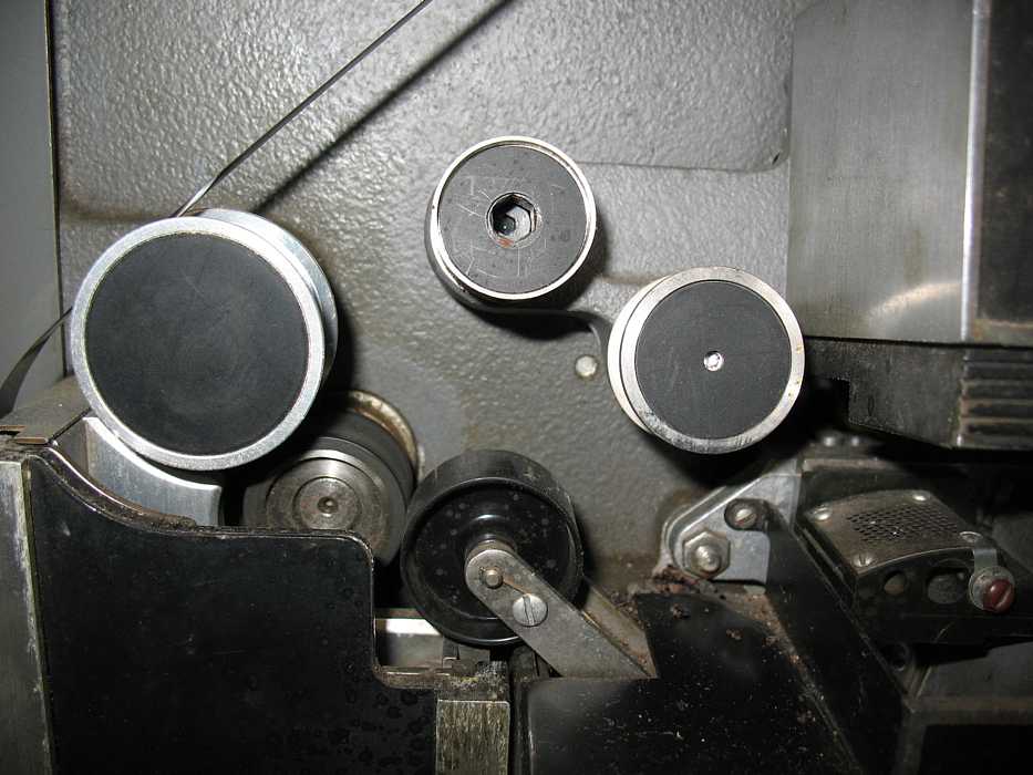
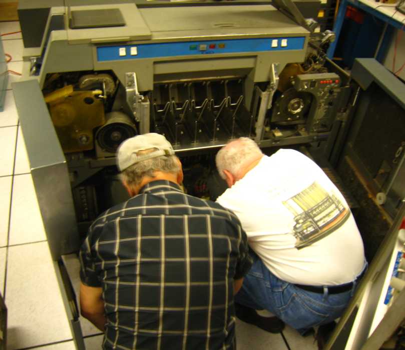
Bill Flora and Stan Paddock were busy laying power and signal cables for the CT (Heck, I can't spell it)
1401. Just look at those heavy things - and be happy with the USB cables connecting
your modern PC ;-))
Ed Thelen continued testing CT 1401 power supplies. These are the power supplies for a machine
thousands of times less powerful than your modern cell phone.
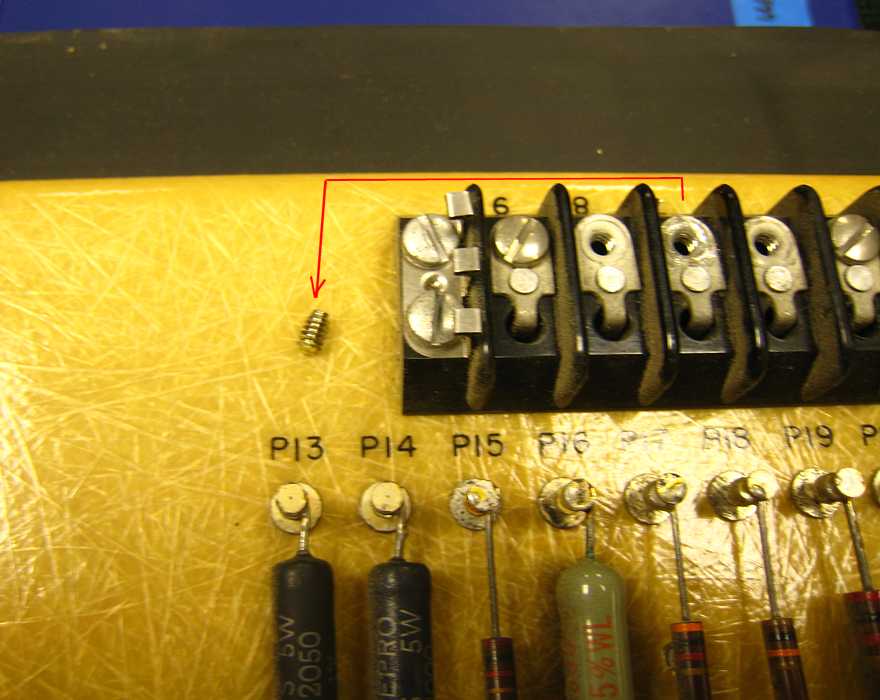
One power supply had a screw with a broken off head. May have caused interesting troubles.
Ron and Stan dug it out :-))
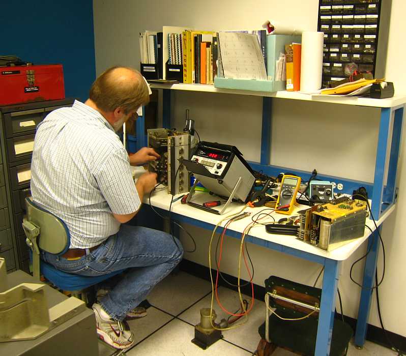
Ed found a power supply that seemed to short at almost no load - but was OK into a 10 megohm load -
Here is Bob Feretich struggling with the odd thing. Turns out the effect was marginal and
intermittent - see next Wednesday -
Just one of those days - almost nobody in top form - except possibly Joe Preston -
who delightedly reported that the # 3 keypunch print mechanism is FINALLY adjusted correctly -
We now have TWO "experts":
(1) Bob Erickson who reluctantly did one for us in 2006, and
(2) Joe
who finished one today.
Bob Erickson reported that frequently a whole region of IBM
would have only one expert of the 026 print mechanisms.

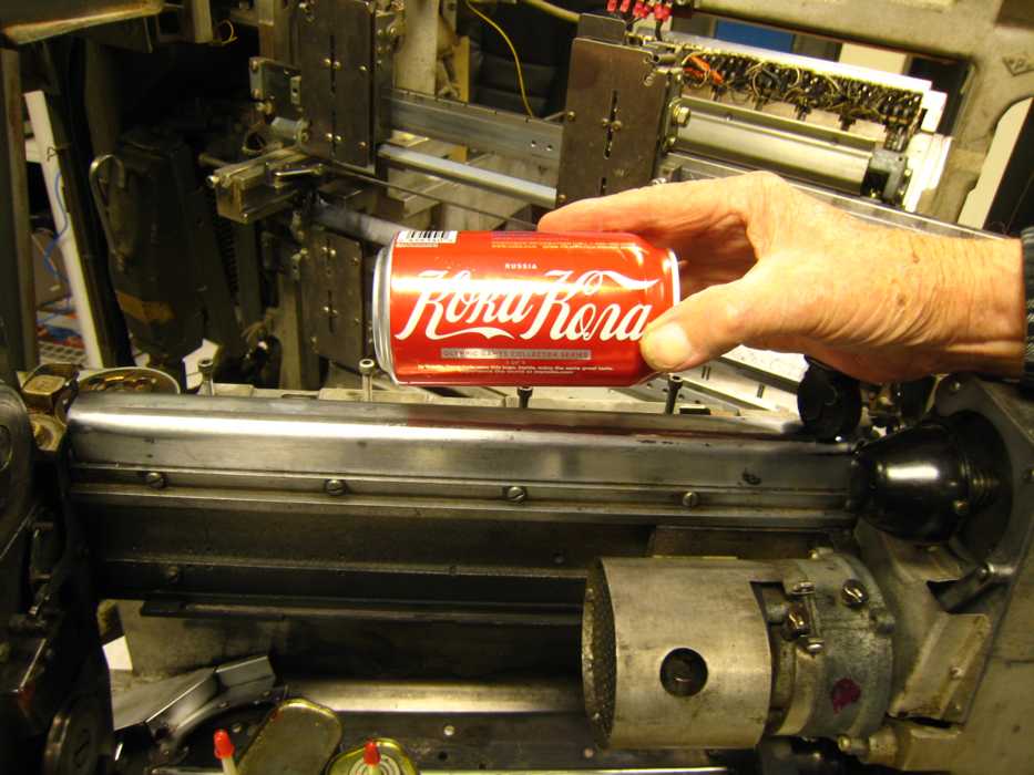
Here are symptoms of our unreadiness to work - Bob Erickson wanted a picture
of this backside of a regular coke can
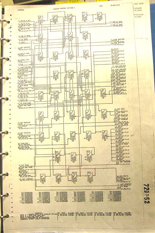
And Ron Williams wants to have this ALD (Automated Logic Diagram) blown up to wall size as a display
And do Ron Williams and Bill Flora look organized?
Well, OK, Frank King was in top form, introducing the 1401 systems to his daughter Carla, who is usually
motorcycling in Russia, China, Greece, ... Carla brought: "Lyn Bishop -
she's a very well known digital artist who combines digital and fine art. She heads up an annual
project at SIGGRAF and gets the latest equipment like large-format printers from Epson, etc. lynbishop.com
[and] Kip Inscore, Peter LaPierre, Jim Inscore."
Frank had mentioned that the drive chain motors in the German and Connecticut 1403 printers were completely
different -
The German (at 50 Hz) had the outside rotating - lots of inertia
The American (at 60 Hz) was the usual form, the inside rotating
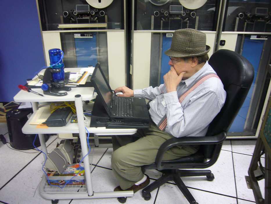
Here is Ed Thelen reading up on "Synchronous Hysterisis Motors" at his "workstation", complete with
microscope, radio to listen to 1401 electrical noise, and 40 watt vacuum tube audio amplifier.
Ron Williams (tongue in cheek???) is suggesting that we appoint a committee to nominate an
action committee to look into making another debug podium and book case, such as used on the
German 1401 (see picture) especially for debugging the Konnektuct (is that really how you spell it?) 1401.
The second -6 volt 12 amp power supply had the same symptoms as the first
-6 volt 12 amp power supply. (The extra power supplies come with the two box 1401 which is the
size we all know and love.)
BUT there was no "Crowbar" card as in the German 1401 !!
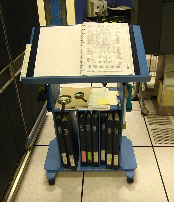
Off we trotted, found the moldy mess (actually not quite that bad, you could separate the pages)
and made archival and working copies of the power-up sequencing and power supplies. :-)))
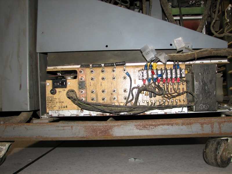
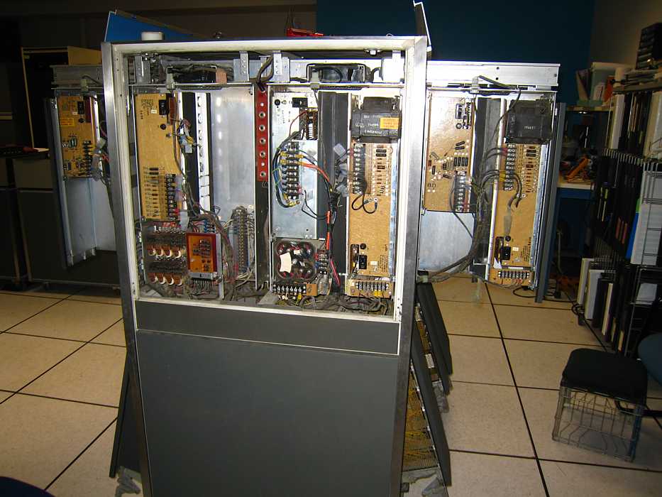
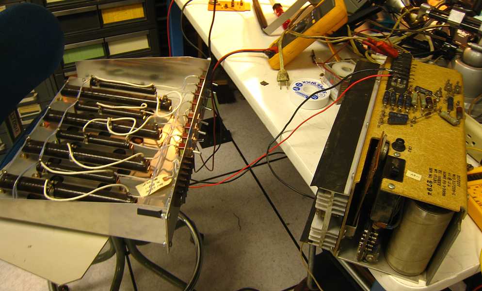
Here is the schematic of the power supply, conservative design for 1958. The incoming 133 volts is from
a ferroresonant regulator, the rectified voltage on the three main filter capacitors is 12 volts -
lots of "head room" for the linear pass transistors to output a regulated 6 volts.
The red boxed areas, "detailed" below, refer to an "OverVoltage Receptacle" - which did not seem to be present!

Mostly out of desperation, I "borrowed" a bank of adjustable load resistors from the PDP-1 group -
no body was there to object ;-)) and set it for 1.4 ohms which was about 1/3 rated load. I connected
it to the - 6 volt power supply - and it worked just fine.
We had forgotten that pass transistors leak some, and at no-load, there was not enough resistance
to drain the leakage, and over voltage occurred tripping the over-voltage circuit and thyristor - which we did
not find !!
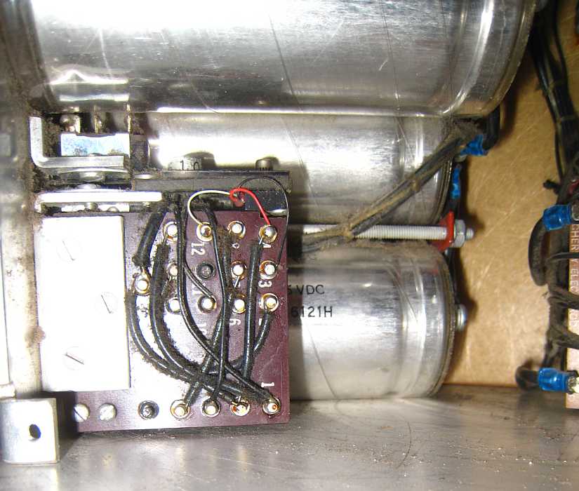
Searching more seriously for some overvoltage and crowbar circuit, I noticed this little assembly
buried in the power supply - it MUST be the optional crowbar circuit !!
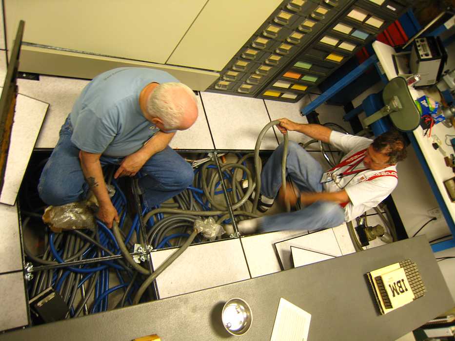
Oh yes, the electrician was in the 1401 room today, studying the three phase 60 amp connectors and
electrical service box.
We ought to have power available to the CT-1401 system "Real Soon Now" :-)))
The 5 vertical telephone jacks between 4) and 5) are for voltage "margining" to help weakening parts fail
to function properly during testing, rather than in service.
1) + 6 volt, 8 amp
2) (hidden) Ferroresonant transformer & capacitors
3) + 30 volt, 7 amp
4) -6 volt, 12 amp
5) + 6 volt, 16 amp
6) -12 volt, 20 amp
7) -6 volt, 12 amp
8) -12 volt, 20 amp

And below identify some "minor" power components and supplies. Will have to ask Ron to help identify -
a) power sequencing relays
b) two power detection cards
c) -
d) -
e) -
f) -
g) -
v) variac
Robert Garner had e-mailed Scott about the CT1401 -
"Ron Williams had a question about this wiring bundle, which looks like an EC that wasn't fully implemented, or something along those lines.
Do you know the history/story behind this loose bundle of wires that was stuffed in behind the front panel?"
Scott responded with

Hey Robert,
Things really sound like they are moving along. It's cool that the tapes are in good shape.
Buzz and I so happy everything is going along as planned.
...
As per the photo with the yellow wires. This is pre Buzz's ownership. He thinks that Genesco had it wired to a tape reader or something along those lines. It never caused him any problems. Check the log books. Buzz thinks that IBM disassembled the system when he bought it. Probably disconnected the wires at that time. Also the system was running good when he shut it down. Broken screw head. That's neat that you were able to find it. Power supplies are good.
So when do you think blast off (power up) is going to be.
I started working on some media ideas to promote Ct1401. If I have any interested parties, I'll give you and Ed a run down before doing anything. If the 1401 team has some ideas, I'm all ears.
I'm also heading up to Ct over the 4th of July. The basement is finally dry. We are going to be getting things more organized. We will be keeping a close eye out for anything that might be needed for the project. Buzz did find this 1401 training manual/book. It's in good shape. It's little things like that, we'll hang onto and not throw away.
One last thing. Per Buzz special request. Can we make up a bio for my brother Ray. He was involved, although on a small level. Just something simple, if its ok. My niece Kendra who is 7 yrs old, I'm sure do some kind of history project on Ct1401, one of these days.
Anyway, that's all for now.
Say "hi" to the team on Wednesday.
Scott
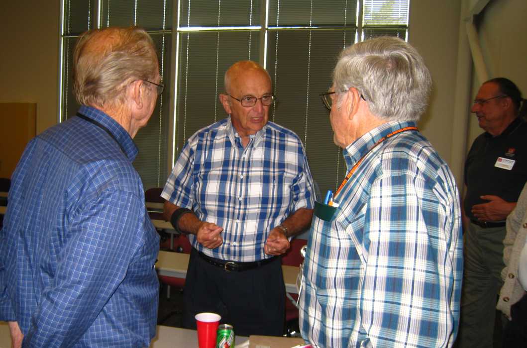
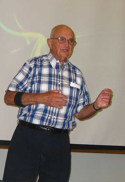
Early birds Bill Flora and Joe Preston listening to our speaker, Shel Jacobs, tell stories in the 1401 room.

Dan McInnis came by. I wondered how to introduce Shel to a programmer, when
Shel called out "Hi Dan" - they had know each other from somewhere in IBM :-)) Shel knew
3 or 4 in our restoration team!!
Present in the Boole Room were:

No - this is not a dismal financial report. We are concentrating on listening
to Fran Underwood on the speaker-phone. Fran was the 1401's lead designer.
Everyone,
- Robert
http://www.theworld.org/?q=node/8152
Fran Underwood talked from his home in Texas. He has had several strokes and does not travel.
His memory and speech is good. He spoke for about 20 minutes from prepared remarks, then responded to many questions from
the audience about the reasons for many decisions in the 1401 system.
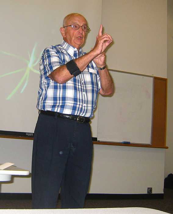
Shel Jacobs is a Great public speaker, he regaled and fascinated us with stories and facts
such as that the 1401 was almost canceled 1 month before formal public announcement.
He discussed why it was almost canceled, and how it was rescued. 5,500 systems were booked within 5 weeks after public
announcement. When asked about whether the 1401 designation had to do with the 1400 characters
of memory available, Shel said the name was purely arbitrary, but IBM was running out of 3 digit names - ...
Says he has hours more of great 1401 stories.
His contact info is in the bio page.
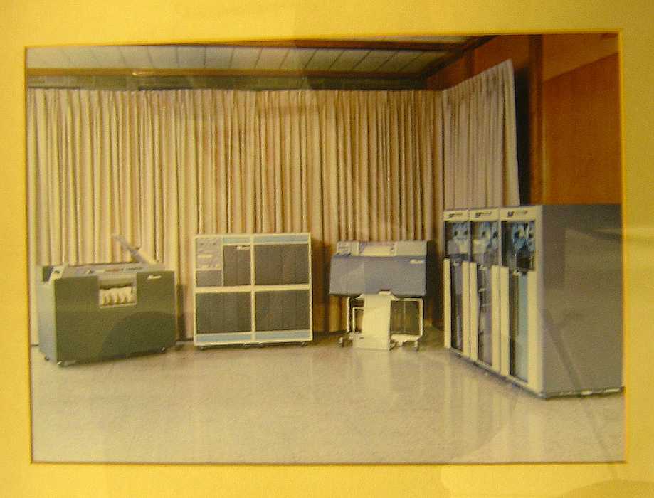
Shel is giving this 1401 PreAnnouncement picture to CHM. Note: no cables - this is a mock-up for photography.
The console lights flash, but not due to 1401 logic. There was only one "working" protytpe.
It was being debugged in the lab - delaying it would delay announcement.
Q&A afterwords :-))