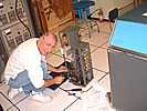
Robert Garner brought in a modern Tekronix four channel storage scope.
I finally asked how much it cost - Robert said something like "You don't
want to know".

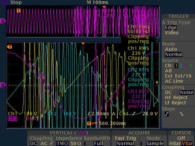
Figure 1.
SteadyState1401
The color codes are PhA=Yellow, PhB=Blue, PhC=Magenta,
from top, middle, bottom Elgar 1750, respectively.
However, note that the phase order on the scope is;
Ā Ā Ā PhA(yellow), PhC(magenta), then PhB(blue).
Why are PhC and PhB reversed in time?
| |
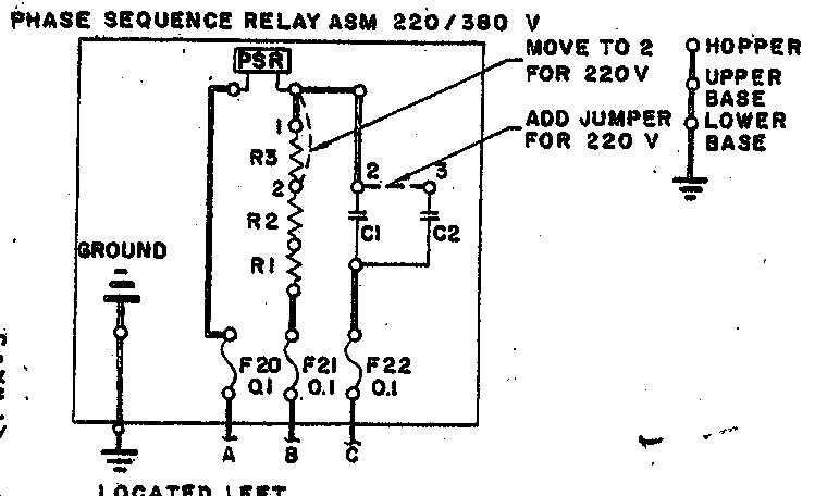
- PhA supplies the 1401-local ferros and thus 1401 DC-supplies,
- PhB supplies a 1.25kW 1402-local ferro for 729's (no load now),
Ā Ā all 1401 fans, and a transformer for convience outlets.
- PhC supplies a ferro for the 1403 (no load now).
The very-high voltage glitches on the Elgar output = 1401's input
as its ferro-resonant supplies are coming up (lasts for ~5 seconds)
look horrible. ĀAfter the startup period, they seem to go away.
However, the last pic shows a steady-state glitch in Phase B,
which is mainly powering the ~36 fans in the 1401.
(The only ferro on PhB is not loaded.)
Here are the surprisingly-high input current and power reading,
which represent an amazing INefficiency, or some other problem.
Also note that "PhC" (the bottom Elgar) rises before "PhB"
(in the middle Elgar) in time on the scope.
|
| PhA Ā | Ā Ā Ā ĀPhB Ā Ā Ā | ĀPhC
| ACInput- No load Ā Ā | Ā Ā 2.1A Ā Ā | Ā Ā 2.7A Ā Ā | Ā Ā 2.9A
| | ACInput-1402 on Ā Ā | Ā Ā 2.9A Ā Ā | Ā Ā 3.6A Ā Ā | Ā Ā 3.7A
| | ACInput-1401 on Ā Ā | Ā Ā20A Ā Ā | Ā Ā25A Ā Ā | Ā Ā24A
| | ACOutput-1401 on Ā | Ā Ā Ā 5.5A Ā | Ā Ā Ā 6.2A Ā Ā | Ā Ā 0.7A
| |
Table 1.
- "ACInput-NoLoad" corresponds to open circuit breaker
Ā Āin the 1402 AC distribution panel. ĀNothing at all is powered!
- "ACInput-1402 On" corresponds to closed 1402 circuit
Ā Ābreaker, but the 1401 off. Ā(Just a transformer for convience
Ā Āoutlets w/10W bulb and a 1.2kW ferro for 729's, not attached.)
- "ACInput-1401 On" is above plus 1401 ferro's, fan's,
Ā Āand DC supplies on. Ā(but no 1406).
Converting to Volts*Amps (watts):
with ACOutput = 220VAC to netural, 50 Hz;
and ACInput = 208VAC to netural, 60Hz.
|
| PhA Ā | Ā Ā Ā ĀPhB Ā Ā Ā | ĀPhC | Total
|
| ACInput- No load Ā Ā | Ā Ā 440VA Ā | Ā Ā Ā 560VA Ā | Ā Ā Ā 600VA Ā | Ā 1.6kVA
|
| ACInput- 1402 on Ā Ā | Ā Ā 600VA Ā | Ā Ā Ā 750VA Ā | Ā Ā Ā 770VA Ā | Ā Ā 2.1kVA
|
| ACInput- 1401 on Ā Ā | Ā Ā4.2kVA Ā | Ā Ā Ā5.2kVA Ā | Ā Ā Ā5.0kVA Ā | Ā Ā14kVA
|
| ACOutput-1401 on Ā | Ā Ā Ā1.2kVA Ā | Ā Ā Ā1.4kVA Ā | Ā Ā Ā 150VA Ā | Ā 2.7kVA
|
Table 2.
The total AC input power of 14kW for only 2.7kW output,
is an efficiency of barely 20%! ĀThat can't be right.
It's also very surprising to me that the 3 Elgars
would dissipate 1.6kW with no output load at all!
Perhaps our output jumpers for 2x voltage are incorrect?
And, of course, after just ~5 mins the wall circuit
breaker trips! Ā At 30A, 208VAC, 3-phase, this correpsonds
to 18.7 kVA of power!! Ā(Perhaps goes up as Elgars warm up.)
- Robert