return to main page

1401 Compatibility Feature on the IBM System/360 Model 30

M. A. McCormack, T. T. Schansman and K. K. Womack
IBM Corporation,* Endicott, New York


Table of Contents
Introduction
The 1401 Compatibility Feature
Implementation
A. CONTROL OF THE 1401 OPERATIONS
1. ROS Control
2. Auxiliary Storage
B. CORE STORAGE
C. CHARACTER REPRESENTATION

Special Considerations
A. SET INSTRUCTION COUNTER
B. SENSE SWITCHES AND START RESET
C. STOP ROUTINE
D. INITIAL PROGRAM LOAD PROCEDURES
Summary


The "second generation" of stored-program computers, of which the IBM 1400 series was a part, brought EDP into the mass market for the first time on a large scale. As this era unfolded, rapid changes in technology led to rapid obsolescence of data processing equipment. Programs written for a particular system required tedious conversion as incompatible :new machines came into use.

The IBM System/360 has been designed with the conversion problem specifically in mind. One of the conversion aids available on the Model 30 is the 1401 compatibility feature. This feature, in conjunction with other aids, permits a smooth and inexpensive transition to optimum use of the new system.

Introduction
In the past it has not generally been economically feasible to implement two dissimilar machine languages within a single processor. Today, the Read Only Storage Controls used in IBM System/360 make it economically feasible to implement the languages of current systems within System/360.

To give as complete a picture of this new implementation technique as possible, remarks will be restricted to implementation of the 1401 compatibility feature on System/360 Model 30.

The 1401 Compatibility Feature Two principal conversion methods have evolved from second generation technology: program translation and simulation.

In considering a method of conversion for 1400 series programs to the Model 30, both of these conversion methods were considered, but were rejected as being either too slow or requiring too much manual intervention. The objective was to provide a means of running 1400 series programs on the Model 30 without change. The introduction of the 1401 compatibility feature on the IBM 1410 had shown historically that such an objective could be achieved in a machine of similar internal organization. Ease of use and speed were demonstrated to be the primary advantages of having a compatibility feature.


In the past, it was considered impossible to implement two completely different machine organizations in one processor, without incurring exceptional costs and intolerable inefficiency. However, in the case of the Model 30, it seemed that Read Only Storage Controls make manipulation of the Processor Data Flow flexible enough to perform 1400 operations at a reasonable rate and at a realistic cost.

For these reasons, the present 1400 series compatibility feature or 1400 series emulator has been developed for the System/360 Model 30. Although generally less efficient than a program specifically written for the new system, the compatibility feature offers a generous increase in speed over the old system. It is, of course, never a solution in itself and should be used in conjunction with other aids as a part of the total conversion approach.

The chief advantages of the compatibility feature are:
  1. The delay in getting the new computer in operation is minimal.
  2. Immediate speed advantages usually can be gained without reprogramming, program translation, or making any changes to existing 1401 programs.
  3. The transition can take place over an indefinite time period, thus permitting gradual and thorough education and preventing the financial expenditure usually associated with "crash" conversions.
  4. Those applications destined to be discontinued can be gracefully and economically "phased out."
  5. Operating personnel can gain experience on the new system console while running familiar programs.
  6. The ability to perform parallel runs, often desirable during conversion, is available and convenient.
  7. The time between order and installation of the new system can be spent on developing new jobs instead of reprogramming old ones.


Of course, a certain amount of degradation in speed cannot be avoided. The data flow of the Model 30 is optimized toward System/360 operations, and there are certain factors that cannot be prevented from affecting speed in the 1401 compatibility implementation. Chief among these are:
  1. The conversion of decimal (1401) storage addresses to a binary value, which is necessary to address System/360 core storage.

  2. The difference in character codes of the 1401 and System/360 causing some character manipulation and translation to take place.
The resulting speed, however in almost every case, is still significantly higher than that of the 1400 system being replaced. This, coupled with the availability of high speed tape units and buffered card equipments means a definite increase in job performance for this feature as compared to the 1400 system being replaced.
Implementation

A. CONTROL OF THE 1401 OPERATIONS. The processing unit of the System/360 Model 30 with the compatibility feature installed can be represented schematically as follows (Figure 1). It should be noted that the 1401 compatibility feature is implemented by adding an additional block of ROS control and by changing a portion of auxiliary storage.

1. ROS Control. The control of the System/360 Model 30 is designed around a read-only storage (ROS), and includes the hardware for addressing the ROS and sensing and decoding the output and the basic clock. It can be represented as shown in Figure 2.

Briefly, the address of a particular ROS word is entered into the Read Only Address Register (ROAR) and a ROS cycle is started. After the addressed word is read from storage into the control register, its contents are decoded and used to activate various control points in the system data flow. A single ROS word combined with a series of timing pulses can be used to control a sequence of events (e.g., add a number in one hardware register to a number in another register and store the result in a third register). Such a sequence of ROS words is known as a microprogram.


A particular ROS word also contains a portion of the address of the next word to be executed. The remainder of the address is obtained from various machine conditions such as the condition of the adder carry latch. This allows branching on machine conditions. The address obtained is entered into the ROAR and a new cycle started, thereby allowing an indefinite sequence of ROS words to be executed.

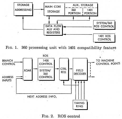
It is possible to microprogram all 1400 instructions except for certain I/0 instructions without any hardware changes in the Model 30. However, certain minor changes have been made in the hardware to speed up the 1400 instruction execution. Timing considerations dictate the addition of some hardware (e.g., Group Mark-Word Mark detection) in order to handle the data rates of some devices.

2. Auxiliary Storage. Auxiliary storage is part of the same storage array as main storage and has a capacity which varies from 512 to 2048 bytes, depending on the size of main storage. It is, however, not addressable by System/360 programs but is in effect part of the 360 controls.

In System/360 mode, 256 bytes of auxiliary storage (these 256 bytes are referred to as local storage) are used for storing such things as General Purpose Registers, Floating Point Registers, and the Condition Register. The remainder of auxiliary storage is used for storage of control words necessary to operate the devices on the Multiplexor channel. The number of control words that can be stored depends on the size of main storage.


Before the processor can be used in 1400 mode, it is necessary to load 512 bytes of auxiliary storage with certain fixed information which is required to absorb the differences in code structure and storage addressing between the 1401 system and System/360. Also, a certain amount of variable information (e.g., tape densities, unit addresses, etc.) must be entered before the microprogram can execute 1400 instructions. A listing and description of some of the tables and information needed in auxiliary storage follows:

a. Decimal to Binary conversion table. As indicated before, the 1400 addresses read from storage have to be converted to a binary equivalent. Tables are provided in auxiliary storage so that a simple table lookup may be used to convert the tens and hundreds digits of the 1401 address to binary.


b. 1400 BCD to System/360 EBCDIC translate table. Although the compatibility feature is designed so that 1400 programs can be kept in EBCDIC code, it is still necessary to convert to 1400 BCD for some 1400 operations. An example of such an operation is "Move Zone." It is not sufficient to merely move the zone portion of a character in EBCDIC. Both the source and destination character are first translated to 1400 BCD, the zone is then moved, and the resultant BCD character is translated to EBCDIC. Another table is provided in auxiliary storage so that the resultant character may be translated from 1400 BCD to System/360 EBCDIC.

c. Operation code translate table. A 64-byte table is stored in auxiliary storage which is used for converting the 1400 operation code to a special form. This is done so that decode of the operation code is simplified and made faster. It provides a means of recognizing those operations (such as Set Word Mark and Store Star) which require special attention during instruction cycles. It also makes it easy to no-op any particular operation code or to make any particular operation code invalid.

d. Miscellaneous Information. Examples of other reformation that is stored in auxiliary storage:
  • 1400 Condition bits (high-low-equal, overflow, etc.).
  • Settings of sense switches.
  • Physical assignment of 1/0 units. (1/0 devices on System/360 have particular unit addresses assigned at time of installation. The addresses of the particular devices to be used by the compatibility feature are entered in the appropriate bytes in auxiliary storage.)
  • System definition bits such as storage size, advanced programming feature, expanded edit, etc.
  • Programmed mode switch control bits for switching from 1401 mode to System/360 mode under program control.
  • Control information for specifying different types of printer chains or bars.


B. CORE STORAGE. 1401 core storage is placed in the upper part of the Model 30 core storage. Except for the 64K Model 30, the 1400 core storage is located at the very top of the Model 30 storage. For example, in an 8K Model 30 (8192 bytes of storage) positions 192 through 8191 would be used to represent 8000 positions of 1401 storage. This has two advantages.
  1. Detection of storage wrap1 when operating in 1401 mode is simplified.
  2. If more core is available than is required for the 1401 operations (e.g., 16,384 bytes of Model 30 storage for 8000 positions of 1400 storage), the Supervisory program in lower core need not be destroyed. This allows the Programmed Mode Switching feature to be used, for example.
For the Model 30 having 65,536 bytes of storage, 1401 storage is normally located 256 bytes from the top of the Model 30 storage. The last 256 bytes of storage are loaded with a special hexadecimal character (SF) which is used to detect 1401 storage wrap. If it is known that the 1401 programs to be run will not generate a wrap condition, then the 1401 core storage may still be located at the very top of storage even in the 65,536 byte case. However, certain wrap conditions will go undetected in this case.

Any size 1401 core storage is available on any size System/360 Model 30 whose core capacity is large enough to contain it.


C. CHARACTER REPRESENTATION. The 1400 BCD characters are represented internally in Extended BCD Interchange Code (EBCDIC). This code is described in the IBM System/360 Principles of Operation. The absence of bit 1 in this code is used to indicate the presence of a word mark. At first glance it might seem unnatural and difficult to implement a character representation different from the one used on the machine to be emulated. However, the difficulties are negligible, and the advantages are significant.

1. It is true that some instructions, such as Branch on Bit Equal or Move Zone lose some speed; other instructions, however, gain significantly in execution time. An example of the latter is the Compare instruction. The bit configuration for the 1400 characters is such that characters have to be compared in a specially designed compare unit. These same characters "mapped" into EBCDIC can be compared with a simple subtract operation, because the bit configuration for EBCDIC forms a binary collating sequence.

The System/360 Model 30, then, does not employ a compare unit. If the 1400 characters were represented in standard 1400 BCD for emulation, a Compare Instruction would require a translation into EBCDIC before performing an arithmetic compare. By representing the 1400 characters directly in EBCDIC the translation becomes unnecessary. The result of this mode of character representation is a general increase in internal performance.

2. Data can be written on Disk Storage or 9-track tape in EBCDIC. This allows for manipulation of bulk storage by either 1400 or System/360 programs without the necessity of programmed or hardware character translation. Note that 7-track tape is always written in standard 1400 BCD, so that it can be used on systems utilizing 7-track tape units in a normal manner. The character translation, in this case, is part of the 7-track feature of the System/360.


Special Considerations

In the design of the 1401 compatibility feature several things had to be given special consideration. The way in which some of these were handled illustrates the flexibility of the ROS control in the Model 30.

A. SET INSTRUCTION COUNTER. The Model 30, when operating in System/360 (2030) mode, has a Set Instruction Counter (Set IC) function. This function, however, is microprogrammed in such a way that the instruction counter is set to the binary instruction address set in the console switches. In 1401 mode, it would be desirable to provide a means of setting the 1401 instruction counter by entering a decimal address in the console switches. Such a means has been provided. A special microprogram was written to allow a decimal address to be dialed in the console switches. (The number of thousands is not entered in pure decimal but is entered on one rotary switch which varies from 0 to 15.)

The special set IC microprogram written for the compatibility feature does the following:
  1. Converts the 1401 decimal address to its equivalent binary value including the proper offset to locate 1401 storage at the top of main storage.
  2. Displays the converted binary address as well as the decimal address in the console display lights.
  3. Displays the character at the address in the console lights.
It should be noted that the function of Set IC has been augmented to provide two additional functions, namely, address conversion and character display.


B. SENSE SWITCHES AND START RESET. The Model 30 does not have console sense switches nor does it provide a key equivalent to the 1401 Start Reset Key. In order to provide these functions in a relatively easily used manner on the Model 30, use was made of the Console Interrupt Key, which otherwise would have no function when operating in 1401 mode. Special microprograms are provided to recognize that the Console Interrupt Key has been pressed while in 1401 mode. One of the console rotary switches is used to select the proper 1401 sense switch and to indicate to the microprogram whether to turn that sense switch control bit on or off. It also has a position which may be used to cause a 1401 Start Reset function to be accomplished.

The same console rotary switch is also used along with the Console Interrupt Key to provide a convenient way to change tape unit densities and unit address assignments. In this case, the 1401 unit address, the tape density for that 1401 unit address, and the System/360 tape drive address assigned to that 1401 tape unit are entered in additional console rotary switches.

C. STOP ROUTINE. A common microprogrammed routine is provided for all stop conditions (except for certain machine malfunctions) that occur while in 1401 mode. Examples of such conditions:
  • Input/Output Error
  • Operator Intervention Required
  • 1401 Programmed Halt
  • Process Check.
Such a routine was written so that as much information as practicable could be provided to the operator when some stop condition occurs. As provided on the Model 30, this routine converts all three 1401 addresses from binary back to decimal and displays the 1401 I-address and A-address in the console display lights. A coded byte is displayed in the console display lights indicating the cause of the stop. It is possible to display the 1401 B-address in a decimal form using the normal Model 30 manual display controls on the console.


D. INITIAL PROGRAM LOAD PROCEDURES. Essentially two methods have been provided for performing a 1401 load operation.
  1. Program entry into 1401 processing after loading of the 512 bytes into auxiliary storage.
  2. Assuming the 512 bytes of auxiliary storage information are loaded, start a special load microprogram from the console.
If the first method is used, a small program is loaded using normal System/360 load procedures along with the 512 bytes of auxiliary storage information required for compatibility feature operation. A special instruction that can be issued by a System/360 program has been microprogrammed. This instruction takes care of loading the 512 bytes of information into auxiliary storage, does the necessary preparations required to operate in 1401 mode, and initiates 1401 instruction processing. This method would normally be used when there are several changes in the 512 bytes of control information needed in order to run a different 1401 program.
The second method can only be used if the 512 bytes of control information have already been loaded by using the first method. If only a few changes are required to the 512 bytes of control information, they may be made from the console. The most frequent changes involve sense switches, tape densities and tape unit address assignment. Provision has been made for easily changing these from the console.

Summary

Although the instruction set, internal code, and design philosophy of the 1400 differ considerably from those used in System/360, it is possible to run 1400 programs on the 2030 due to the inherent flexibility of the ROS control approach.


Footnotes

1 A 1400-series program would get a storage wrap condition on a 1400 series machine when an address was incremented past available core storage or decremented below 1400 zero.


return to main page