Computers of the 1950 through the 1980 were very three dimensional, and layout of the various functions was also very important.
So, just where do you start to look for the optional multiply/divide in a 1401? This is vital if you are a Customer Engineer facing a customer needing to get payroll out "right now", the folks are waiting for their pay checks. A random walk through the 32 "gates" of the computer seems a poor way to start.
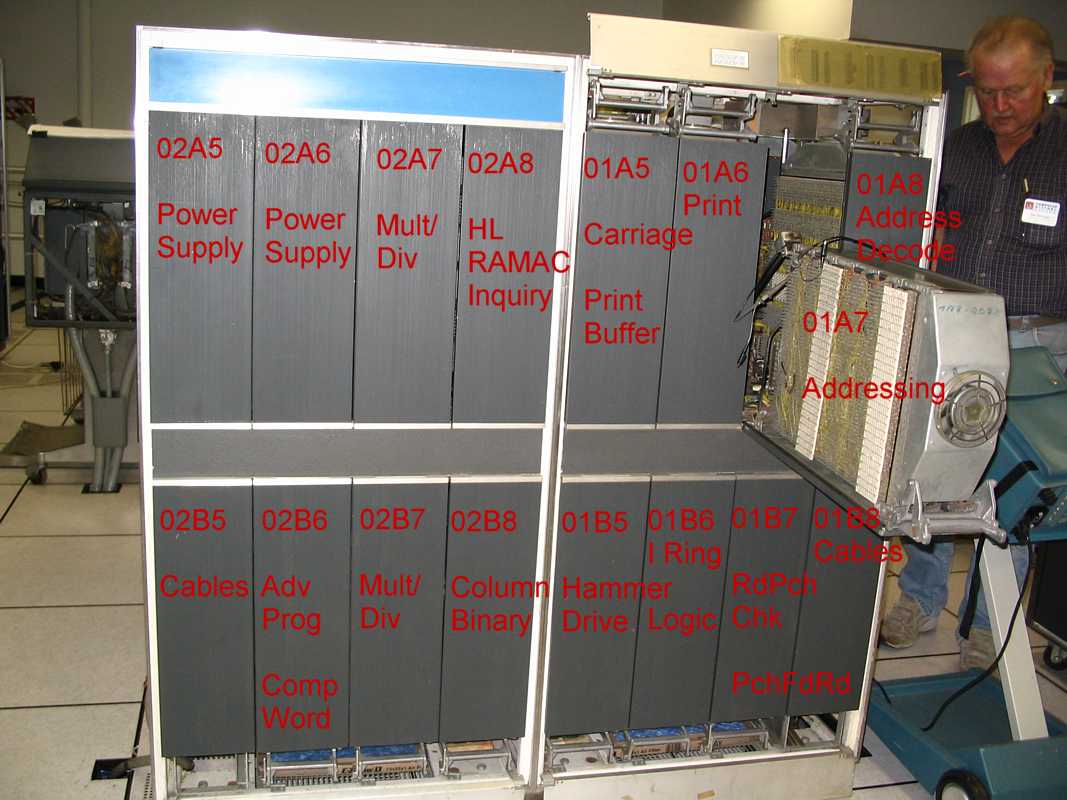
| Here is the back side of our 1401. Ron Williams trouble shooting a problem. Actually at this time the 1401 has many problems, but you have to start somewhere! There are 16 logic swing out units called "gates" on this side of the 1401. The two gates at the upper left contain power supplies, not computer logic. |
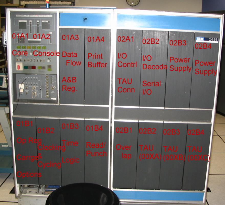
| And here is the more familiar front side, with the operator's console. Notice the core memory is back of the operator's console. On the right hand side you notice three and 1/2 "gates" are labeled "TAU" for Tape Adaptor Unit. The tape drives sent the amplified tape read signals down the cable, and this tape controller had to figure it all out. |

| And this is a document to aid the Customer Engineer to get a rapid start. Function, position (as if he could forget in 40 years?, and the starting sequence number of the AutomatedLogicDiagrams that discribed the machine down to the circuit card and pin. |
Details of the location of each type of circuit card, (SMS card), is here.
Sorry about the picture quality. Trying to get the picture size down for fast loading got a bit overdone.
return to main page